Your TAD kit should come in a bag with a parts layout diagram and parts list on it.

Check the parts against the parts list.

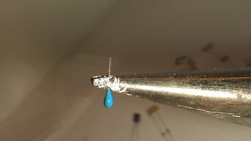
We will start out with the 22pf load capacitors for the crystals. In the first batches of kits we marked these with a silver sharpie.

Next we will put in the crystals themselves. Makes sure the numbers match up.

Next we will add the sockets for each processor. Note that they both face in different directions.

The legs on the 1uf charge pump cap for the pic are a bit wonkey so we straighten them

Once we do that it does very nicely into place.

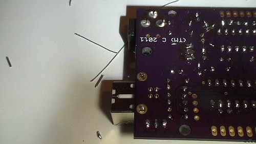
The remaining 5 caps are .1 uf decoupling caps. Here you can see them soldered in and ready to be nipped.

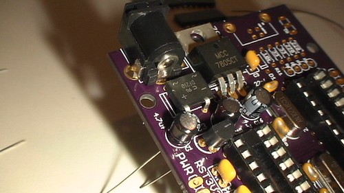
The power section includes a 7805, A jack, a rectifier, 3 electrolytic caps and a 3.3v regulator.

Make sure that you pay attention to the polarity on the caps (long leg in the hole marked +).

Next populate the diode to protect the usb from the external power as well as the 10 k reset pullup for the pic reset. The 33 ohm resistors are for the usb data lines. The next two resistors are the current limiting resistors for the led.

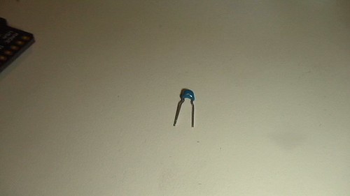
Speaking of the led put the duo-led into the board so that the flat face faces the front of the board.

Then put on the usb header.


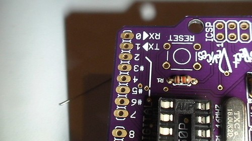
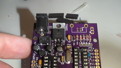
At the other end of the board place the reset pullup for the avr and the the switch. The switch has a dual purpose. If you hold the switch down when plugging the usb into the TAD the pic enters a hid based bootloader.

next to the reset switch is the 6 pin programming header for the avr. Solder that and the headers for the power and analog.

On the other side there is the two 8 pin headers for the data pins.

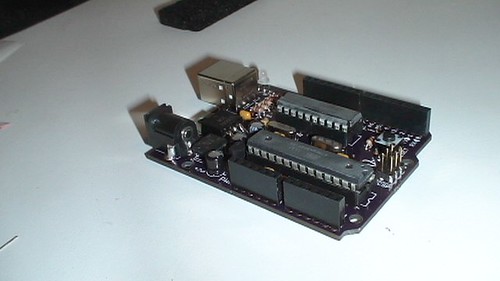
Then seat the processors and and here we are done.

5 Responses to “Tad Buildout”

  1. Stephen Klingenberg

    Hi Don,

    Some time ago (last year) I bought a TAD and just got around to building it. I did a quick inventory of the parts in the bag but not very thorough it seems. I noticed I received some extra parts and have some missing. I got an extra 16mhz crystal, .1uf cap, and 2 220 ohm resistors. What I am missing is: the USB connector, the power connector, and the 33 ohm resistors (2). The power connector isn’t a problem because I have an extra from another project but I need the USB conn. I may be able to substitute the 33ohm resistors but I don’t have a schematic to know what they are used for. I would gladly send the extra parts back but wondered if you could help with the USB connector and the 33 ohm resistors. I live in Vancouver (WA) so Im not to far away. I would be willing to purchase the parts but thought you should know.

    Any help would be appreciated. BTW My Duce is working Great!

    Stephen

    • feurig

      Stephen,
      We tried to email you about this directly so we could get you the parts but the email you signed in with bounces.
      Don

      • feurig

        Also I will see where the schematic is posted and link to it here.

  2. Ken

    Love it! You are not a true Arduinoist until you make your own! Wait, that was Jedi and light sabers. Never mind. Took me about an hour to assemble. Instructions are clear. Design is solid. No wanky work arounds (like my projects always end up with). Drivers downloaded automatically. Just had to figure out to use “Duemilanove 328” setting. Just wondering what other functionality the bi-color LED is hiding. Thanks for making the kit!

Leave a Reply to Stephen Klingenberg

  • (will not be published)