This site has been a security liability for over a decade now. I just want to get the content (which is the consolidation of content from 20 years and 3 CMSs). The plugins for static site generation are either an invitation to upgrade to Pro or don’t work.
I will link to whatever works here once I am successful.
If its social then scrape it and automate it. God knows they do.
It’s your work.
They can’t own what you learn.
Redact and copy your notes in Triplicate.
Create/test and share open source gists/solutions
Make work pathways to give back to the community
If you have to learn it you best use it at home (lxd5/ansible/jellyfish/usw)
Work on one less thing (simplify).
Every convenience is a point of failure or an attack surface.
Git does not need to look good to be usefull. (–gitea, –gitlab, ++bare-git+hooks/mirrors)
— Twitter
with or without musk
also #fuckthatguy).
If your content is usefull it will recieve the appropriate tweets, links, usw.
and if it doesnt the internet is fundamentally broken.
If your wysywig is so unusable you don’t “blog” Throw it away. (–wordpress)
Home is where the heart is.
Don’t let pi/routers do server/container work.
PiHole (filtering dns)
dhcp
look at virtualized routing
If you can’t netboot off of it is it really your network.
Same goes for centralized management (ldap).
dhcp
tftp
iscsi
All active work behind at least one firewall.
Automate pushes (including this site).
Streamline/cleanup html generation
It should also be replicated in at least one other location
Let’s go to your place.
Ticketing systems should be more like distributed punchnotecards. –trac
You shouldnt be giving out XXX bucks a month to post your public images so they can be “distributed”
flicker free
multi homed
Just because you have source control doesnt mean it’s all code
use markdown/git for most things.
but focus on the english.
Work imitates life
(What problems are we trying to solve)
Minimize technical debt both past and future.
Disentangle the various interconnected pieces and dependencies
Automate as much as possible
Document what is to be done. (Specification and sample implimentation)
Experience based stepwise refinement.
Sarcasms (link them later)
See: Tufte’s critiq of power point.
“as code” is only as good as the management understanding of the job of the people actually write and maintain it minus corporate whims, the abuse of executive privilege, and cultural constraints..
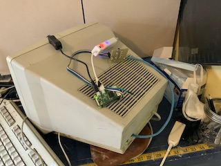
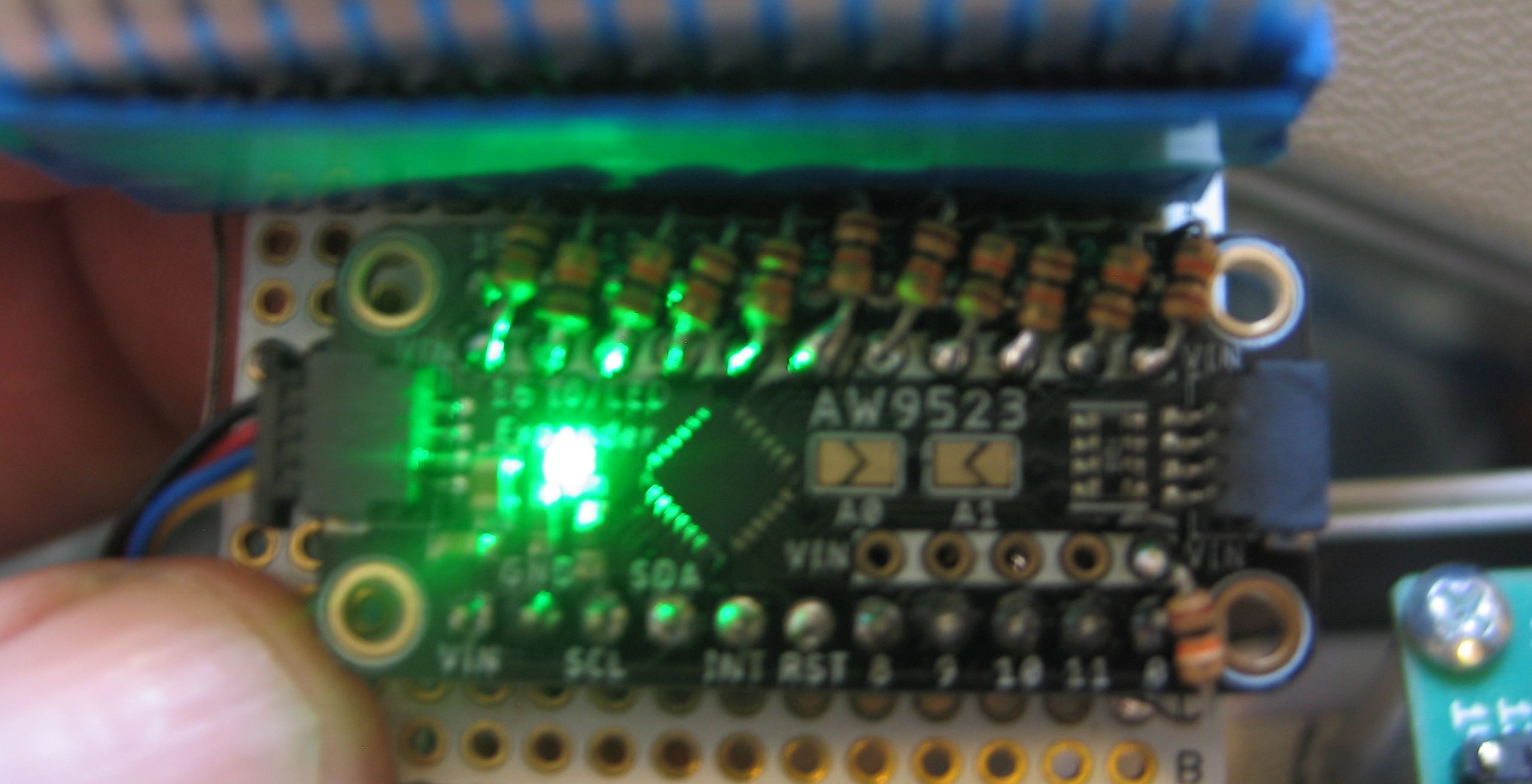
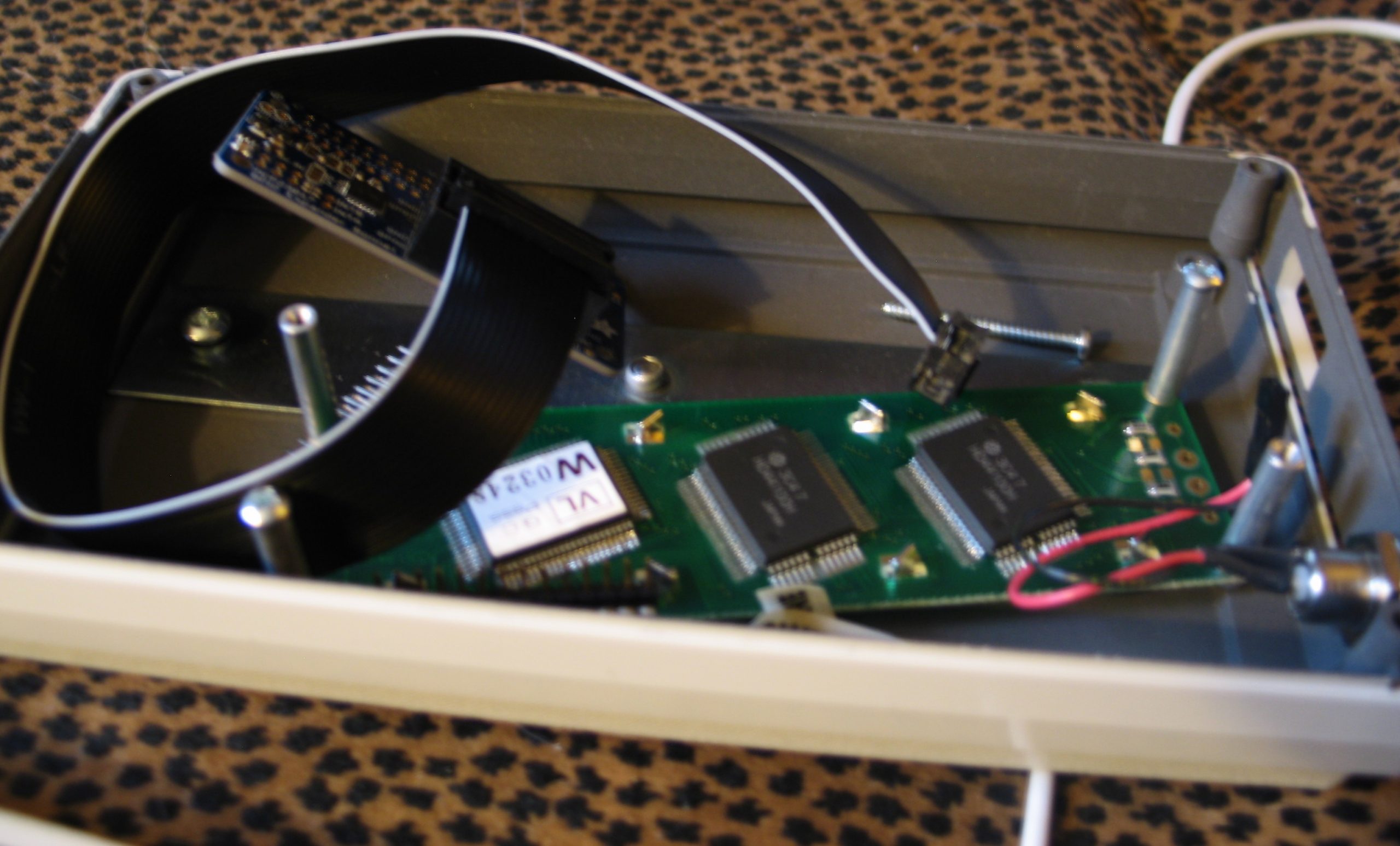
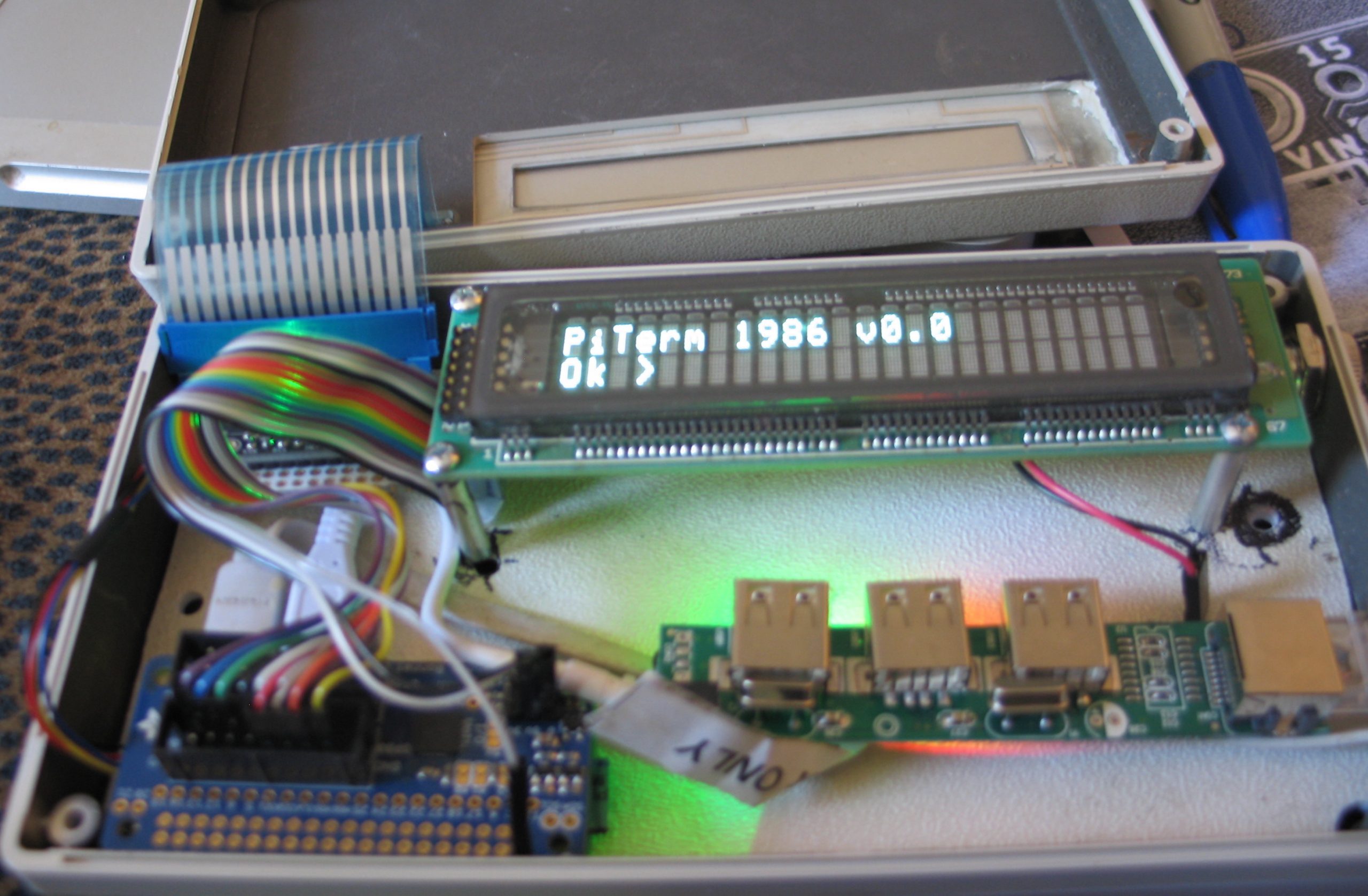
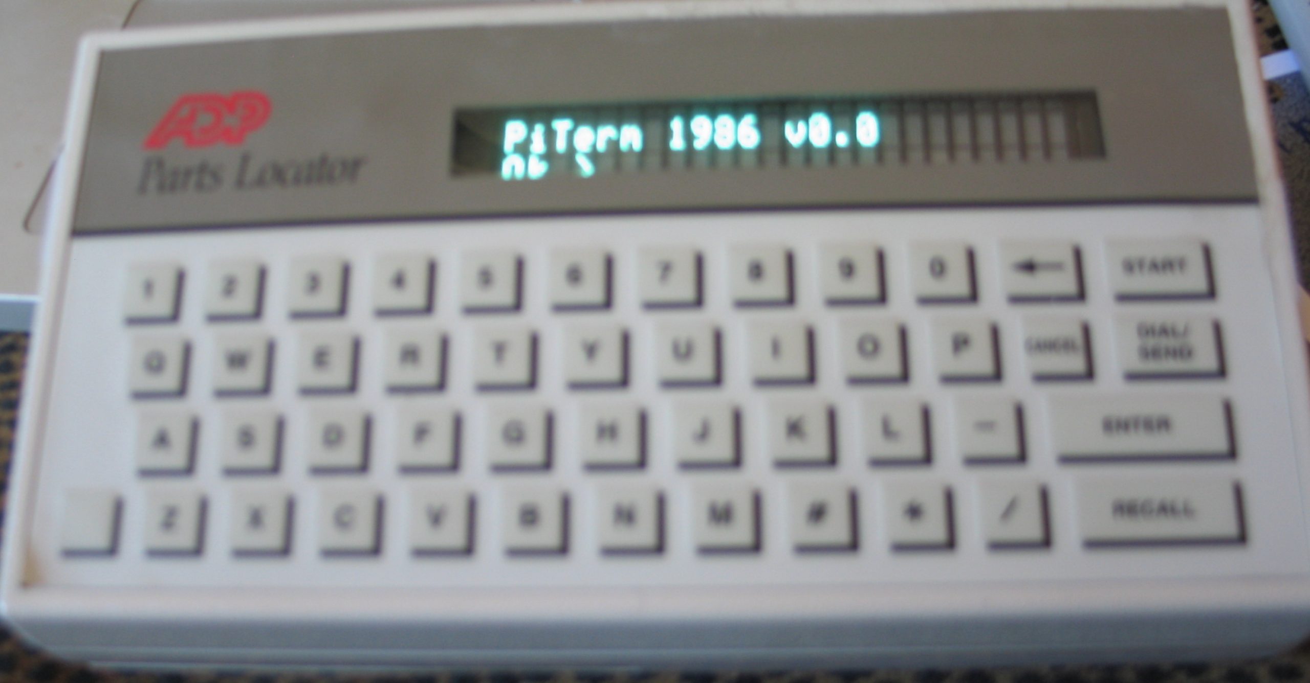
In our last post we talked about wanting explore the use of two I2C based io expanders in an old school application. If it werent for the fact that there was a readymade lcd library for the mcp23017 I would have swapped the io expanders. No Pull-ups, No Pulldowns and no decent documentation on the circuitpython libraries makes the AW9523 a sucky choice for an old school keyboard matrix. But Hey, F**k It Dog. Life’s A Risk. We are gonna make do with what we have.
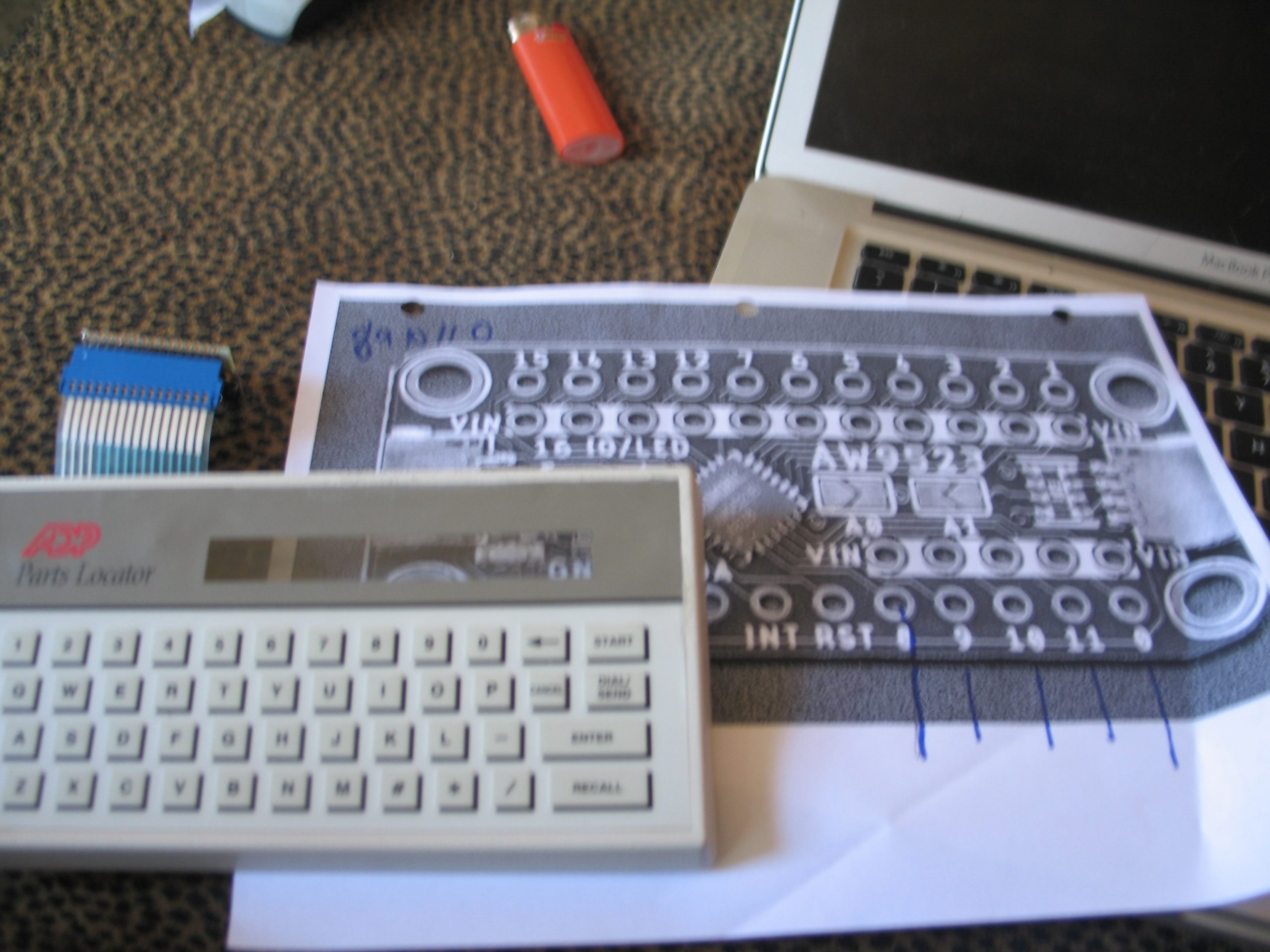
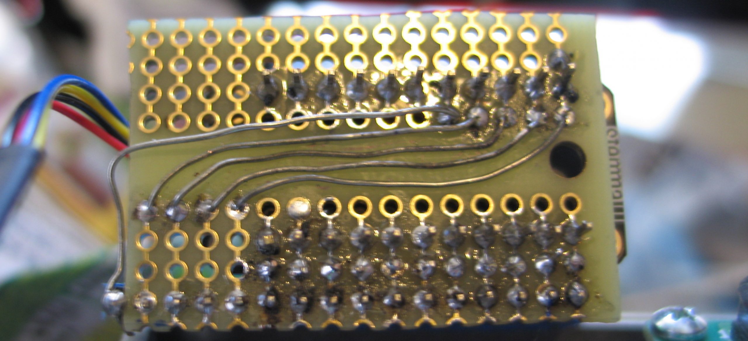
Looking under the keyboard membrane and tracing the connectors we can get the following key map under a 4×12 array (16 pins).
Of course for this to work we needed to solder 10k pull up resistors on all but the last 4 pins (8-11). This was relatively straightforward since there is a strip of connectors to VIN on the board. Still, kind of a pain. On the other hand I have reals of 10k resistors and I guess I have time.
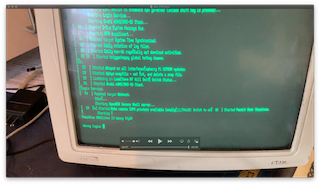
Here is a simple circtuitpython program which presents a prompt and then puts characters scanned by the keyboard onto the display.
import time
import board
import busio
import adafruit_character_lcd.character_lcd_rgb_i2c as character_lcd
import adafruit_aw9523

keymap=[]
keymap.append('*# ZXCVBNM/\001')
keymap.append('-LASDFGHJK\r\n')
keymap.append('0912345678\010\002')
keymap.append('POQWERTYUI\030\004')

lcd_columns = 24
lcd_rows = 2
i2c = busio.I2C(board.SCL, board.SDA)
lcd = character_lcd.Character_LCD_RGB_I2C(i2c, lcd_columns, lcd_rows)
lcd.message = "PiTerm 1986 v0.0\nOk >"

aw = adafruit_aw9523.AW9523(i2c)
row_pins = [aw.get_pin(8),aw.get_pin(9),aw.get_pin(10),aw.get_pin(11)]
for pin in row_pins:
   pin.switch_to_output(value=True)

col_pins = [aw.get_pin(0),aw.get_pin(15),aw.get_pin(14),aw.get_pin(13),
            aw.get_pin(12),aw.get_pin(7),aw.get_pin(6),aw.get_pin(5),
            aw.get_pin(4),aw.get_pin(3),aw.get_pin(2),aw.get_pin(1)]

for pin in col_pins:
   pin.switch_to_input(value=True)


old_row=0;
for pin in row_pins:
    pin.value=1

switch_state = [[0,0,0,0,0,0,0,0,0,0,0,0],
                [0,0,0,0,0,0,0,0,0,0,0,0],
                [0,0,0,0,0,0,0,0,0,0,0,0],
                [0,0,0,0,0,0,0,0,0,0,0,0]
               ]
while True:
    for r in range(4):
        row_pins[old_row].value=1
        row_pins[r].value=0
        old_row=r
        for c in range(12):
            if (col_pins[c].value==0 and switch_state[r][c]==0):
                switch_state[r][c]=1
                print(keymap[r][c])
                lcd.message+=keymap[r][c]
            if (col_pins[c].value==1 and switch_state[r][c]==1):
                switch_state[r][c]=0
    time.sleep(0.01)  # debounce
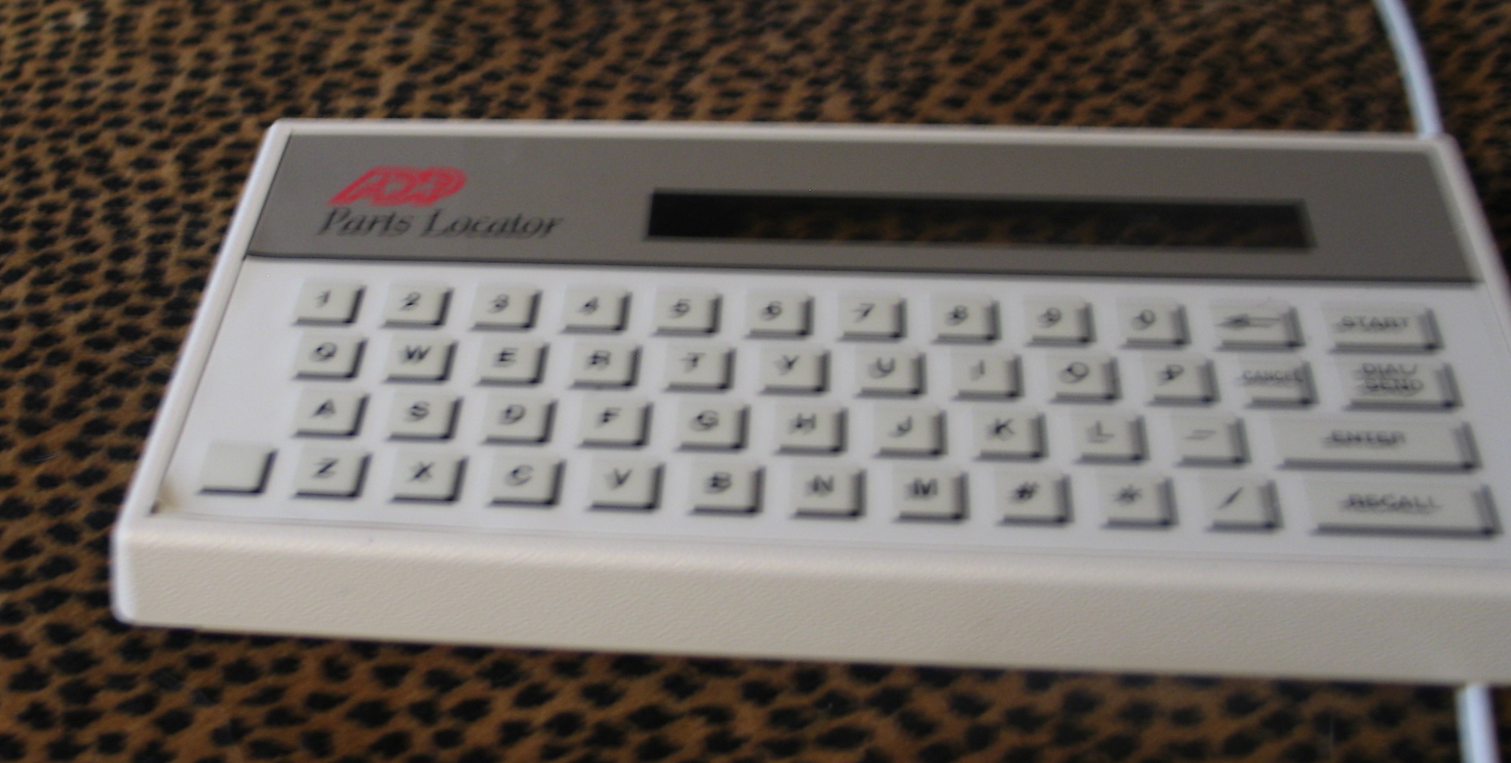
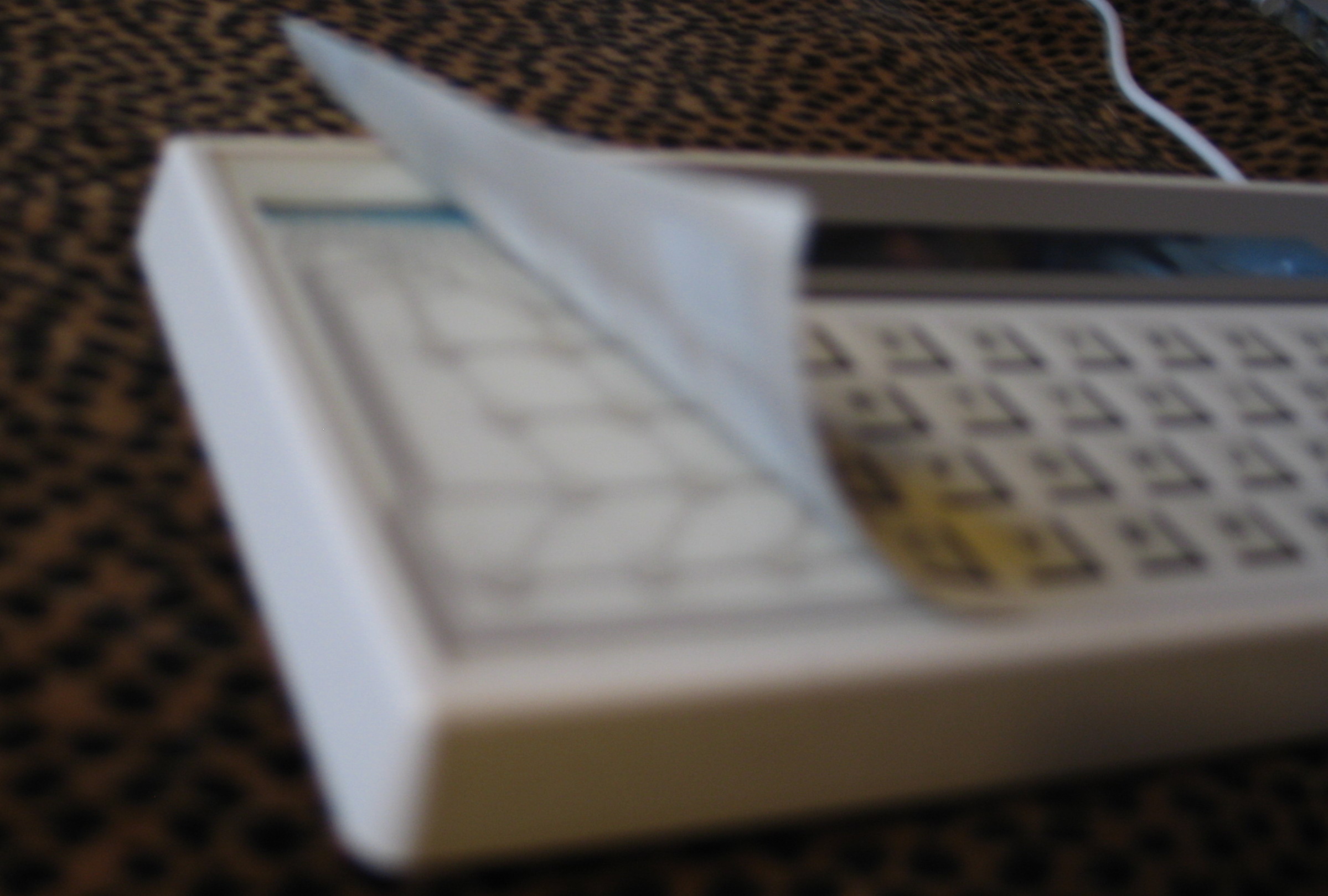
GOAL: Convert 80s style user interface ( 8031 based ADP Product: chicklet keyboard and 2×20 lcd ) to pi zero based terminal using i2c based io expanders.
Looking under the keyboard membrane and tracing the connectors we can get the following key map under a 4×12 array (16 pins).
For this we look at the AW9523 GPIO expander with 16 pins of io.
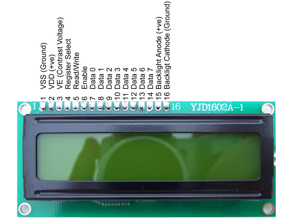
LCD/VFD
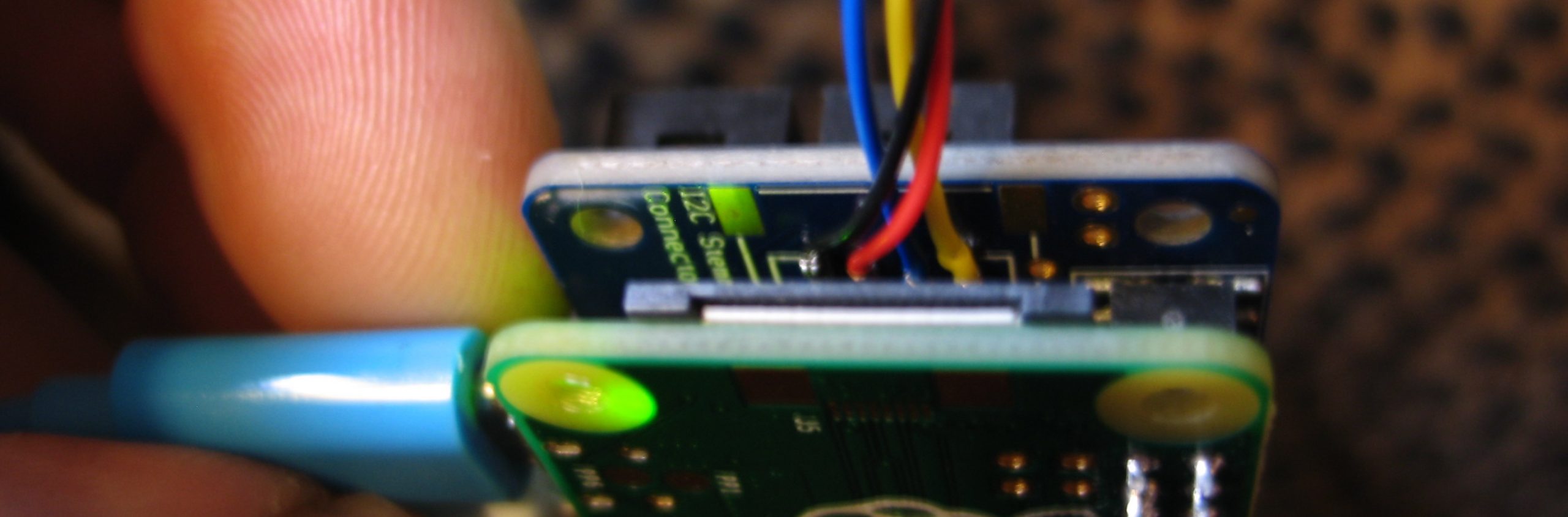
Since the LCD is a 5v circuit requiring either 8 or 12 pins we look at the Microchip MCP23017 on the Adafruit GPIO Expander Bonnet which we can wire either using both ports or one port in nibble mode.
After putting the board in the box I realized that the grey paint was conductive and that I almost let the smoke out of the pi zero. (you could smell it). So I went out and found a piece of plastic from a previous project.
And then I was like OH SHIT I have Noritake 2×24 VFD thats a close fit..
So there’s a circuitpython library for an mcp23017 connected to an lcd. Wiring it up according to the above schematic lets us write away
I was going to explain how we got here but. Nah. It is what it is.
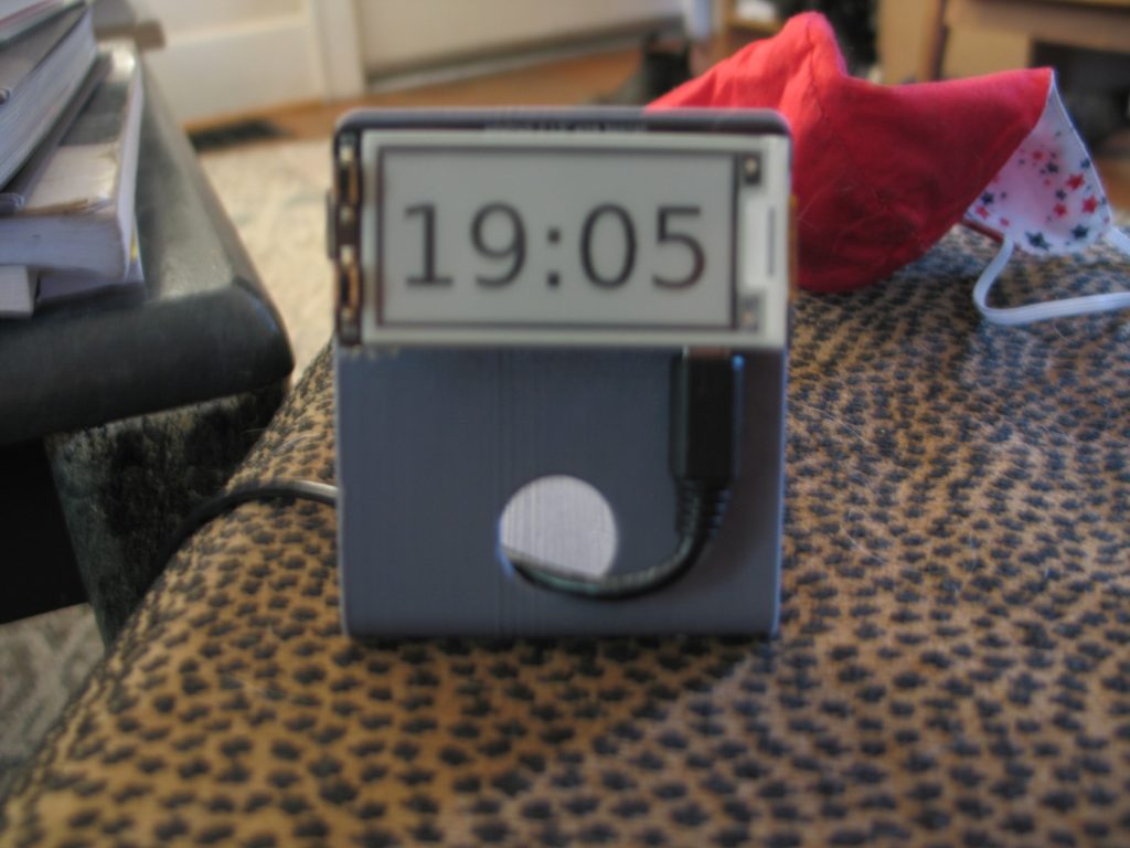
#---------------------------------------------------------------epaperisslow.py
# playing around with 2.13" HD mono pi hat.
# references adafruit example code.
# screen drawing takes 9-10 seconds per update.


from datetime import datetime

def TimeString ():
    return datetime.now().strftime("%H:%M")

import time
import busio
import board
from digitalio import DigitalInOut, Direction

from PIL import Image
from PIL import ImageDraw
from PIL import ImageFont
from adafruit_epd.epd import Adafruit_EPD
from adafruit_epd.ssd1675b import Adafruit_SSD1675B
import math
import random


# create two buttons
switch1 = DigitalInOut(board.D6)
switch2 = DigitalInOut(board.D5)
switch1.direction = Direction.INPUT
switch2.direction = Direction.INPUT

# create the spi device and pins we will need
spi = busio.SPI(board.SCK, MOSI=board.MOSI, MISO=board.MISO)
ecs = DigitalInOut(board.CE0) ## check back on this
dc = DigitalInOut(board.D22)
rst = DigitalInOut(board.D27)
busy = DigitalInOut(board.D17)

# give them all to our driver
display = Adafruit_SSD1675B(
    122,
    250,
    spi,  # 2.13" HD mono display (rev B)
    cs_pin=ecs,
    dc_pin=dc,
    sramcs_pin=None,
    rst_pin=rst,
    busy_pin=busy,
)
display.rotation = 1

# Create blank image for drawing.
# Make sure to create image with mode '1' for 1-bit color.
width = display.width
height = display.height
lightimage = Image.new("RGB", (width, height))
darkimage = Image.new("RGB", (width, height))

WHITE = (0xFF, 0xFF, 0xFF)
BLACK = (0x00, 0x00, 0x00)
print("clearing display")
# clear the buffer
display.fill(Adafruit_EPD.WHITE)
# clear it out
display.display()

# Get drawing object to draw on image.
light = ImageDraw.Draw(lightimage)
dark = ImageDraw.Draw(darkimage)
# empty it
light.rectangle((0, 0, width, height), fill=WHITE)
dark.rectangle((0, 0, width, height), fill=BLACK)
print("drawing box")

# Draw an outline box
light.rectangle((1, 1, width - 2, height - 2), outline=BLACK, fill=WHITE)
# Draw some shapes.
# First define some constants to allow easy resizing of shapes.
padding = 5
shape_width = 30
top = padding
bottom = height - padding
# Move left to right keeping track of the current x position for drawing shapes.
x = padding

# Load default font.

font = ImageFont.truetype("/usr/share/fonts/truetype/dejavu/DejaVuSans.ttf", 80)

text_origin=(7,top+15)
light.text(text_origin, TimeString(), font=font, fill=BLACK)
dark.text(text_origin, TimeString(), font=font, fill=WHITE)

print("entering the loops")

#display.image(darkimage)
#display.display()

old_ticks = time.monotonic() - 50.0
image2display=darkimage

while True:
    ticks = time.monotonic()
    # if programmer is bored: move this section to an interrupt
    if not switch1.value:
        print("Switch 1")
        image2display=lightimage
        display.image(image2display)
        display.display()
        #No point in debouncing after the display takes 9 seconds
        #while not switch1.value:
        #    time.sleep(0.01)

    if not switch2.value:
        print("Switch 2")
        image2display=darkimage
        display.image(image2display)
        display.display()
        #No point in debouncing after the display takes 9 seconds
        #while not switch2.value:
        #    time.sleep(0.01)

    # print( ticks - old_ticks)

    # Update the time on both dark and light images.
    if(( ticks  - old_ticks) >= 50.0):
        #current_time=datetime.now().strftime("%H:%M  ")
        print("updating "+TimeString())
        light.rectangle((0, 0, width, height), fill=WHITE)
        dark.rectangle((0, 0, width, height), fill=BLACK)
        light.rectangle((1, 1, width - 2, height - 2), outline=BLACK, fill=WHITE)
        light.text(text_origin,TimeString(),font=font, fill=BLACK)
        dark.text(text_origin,TimeString(), font=font, fill=WHITE)
        display.image(image2display)
        display.display()
        old_ticks=time.monotonic()
feurig@figaro:~/raspi-python-playground $ cat /etc/rc.local
#!/bin/sh -e
# turn off the on board led and start the clock
echo 0 > /sys/class/leds/led0/brightness
python3 /home/feurig/raspi-python-playground/epaperisslow.py
exit 0
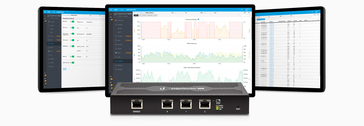
In our deployment the router is maintained externally. For this reason direct login to the router as root is disabled and sudo enabled accounts are installed. These accounts connect using ssh keys and escallate privilages with their passwords. The root account is locked and ssh access is allowed from the wan port. The process for this is documented here
Once this is done the configuration can be saved to a tarball and added to the build under the files directory. These files are copied into the root filesystem of the target. The box then comes up pre configured and pre-hardened. One kludge used here is to add an rc.local which changes the users home directorys to be owned by them. Otherwise the ssh keys will not have the correct permissions.
Also /etc/sudoers, /etc/rc.local, and /home should be added to /etc/sysupgrade.conf. This way the configuration changes will be preserved while doing a sysupgrade
Rebuilding using a repo.
Now that we have a working pre-hardened build for our router we can adjust and repeat the build. (this example assumes that the build server has access to the repo)
feurig@vasily:~$ cd openwrt
feurig@vasily:~/openwrt$ git pull . v19.07.3
feurig@vasily:~/openwrt$ mv files /tmp/
feurig@vasily:~/openwrt$ git clone git@bitbucket.org:houselan/config.git files
Cloning into 'files'...
feurig@vasily:~/openwrt$ cp files/openwrt-octeon-erlite-ext4-sysupgrade.diffconfig .config
feurig@vasily:~/openwrt$ make defconfig
#
# configuration written to .config
#
feurig@vasily:~/openwrt$ ./scripts/feeds update -a
...
feurig@vasily:~/openwrt$ ./scripts/feeds install -a
...
feurig@vasily:~/openwrt$ make -j8 download world
feurig@vasily:~/openwrt$ mv bin/targets/octeon/generic/openwrt-octeon-erlite-ext4-sysupgrade.tar.gz ~/firmware/
feurig@vasily:~/openwrt$ ./scripts/diffconfig.sh > ../firmware/openwrt-octeon-erlite-ext4-sysupgrade.diffconfig
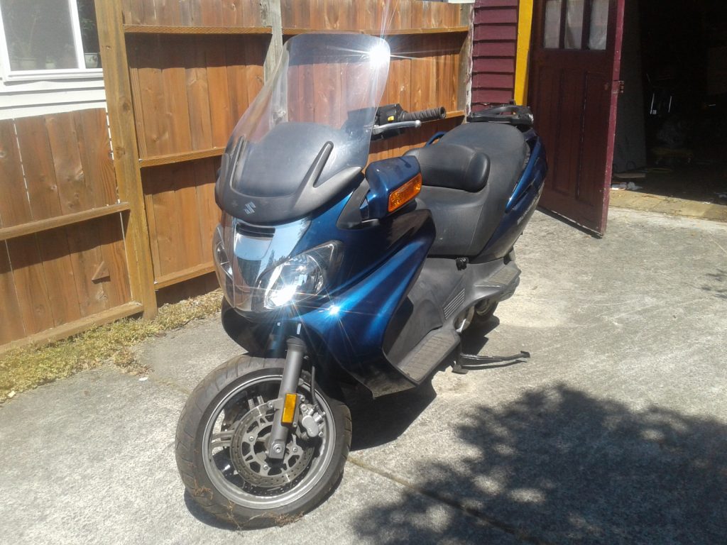
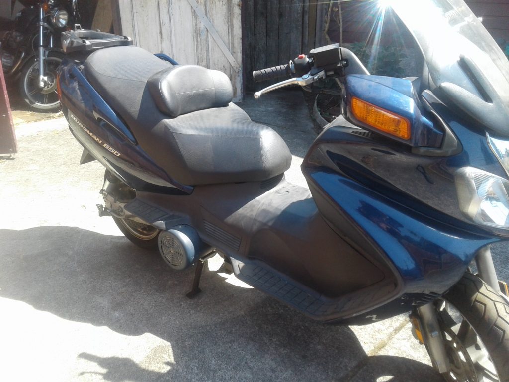
Last time the government gave me a significant amount of unexpected money I bought a sporterized mac 90 (a semiautomatic ak-47). This time I decided to join a different revolution. With a projected cap of $1200 I asked a friend to help me pick parts for converting a Yamaha 850 tripple to electric.
He remembered a conversion that he had helped with and now I have a complete but currently non running conversion of a 2003 Suzuki Bergman 650