In our last post we talked about wanting explore the use of two I2C based io expanders in an old school application. If it werent for the fact that there was a readymade lcd library for the mcp23017 I would have swapped the io expanders. No Pull-ups, No Pulldowns and no decent documentation on the circuitpython libraries makes the AW9523 a sucky choice for an old school keyboard matrix. But Hey, F**k It Dog. Life’s A Risk. We are gonna make do with what we have.
Looking under the keyboard membrane and tracing the connectors we can get the following key map under a 4×12 array (16 pins).
   0123456789A(10)B(11)
   --------------------
0) *# ZXCVBNM/    <STOP>
1) -LASDFGHJK<N/C><ENTER>
2) 0912345678<BS> <START>
3) POQWERTYUI<CAN><DIAL>| * | # | Z | X | C | V | B | N | M | / | STOP | |
| – | L | A | S | D | F | G | H | J | K | N/C | ENTER |
| 0 | 9 | 1 | 2 | 3 | 4 | 5 | 6 | 7 | 8 | <—- | START |
| P | O | Q | W | E | R | T | Y | U | I | CANCEL | DIAL |
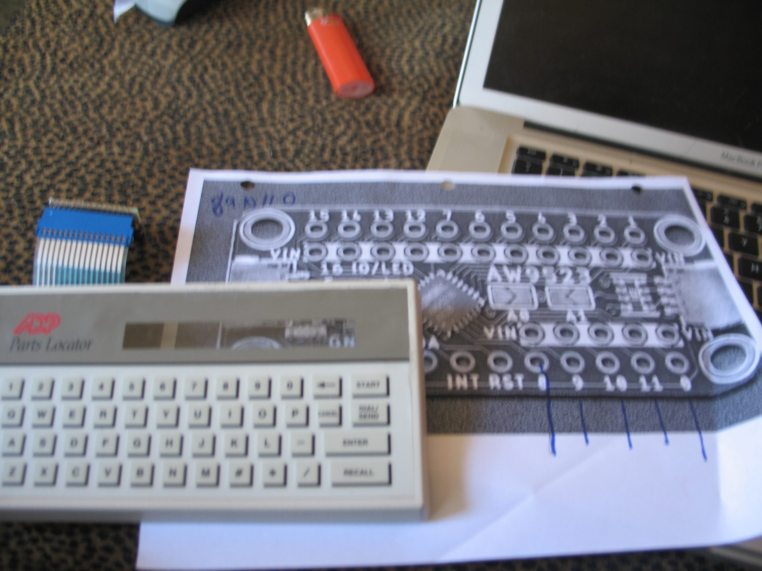
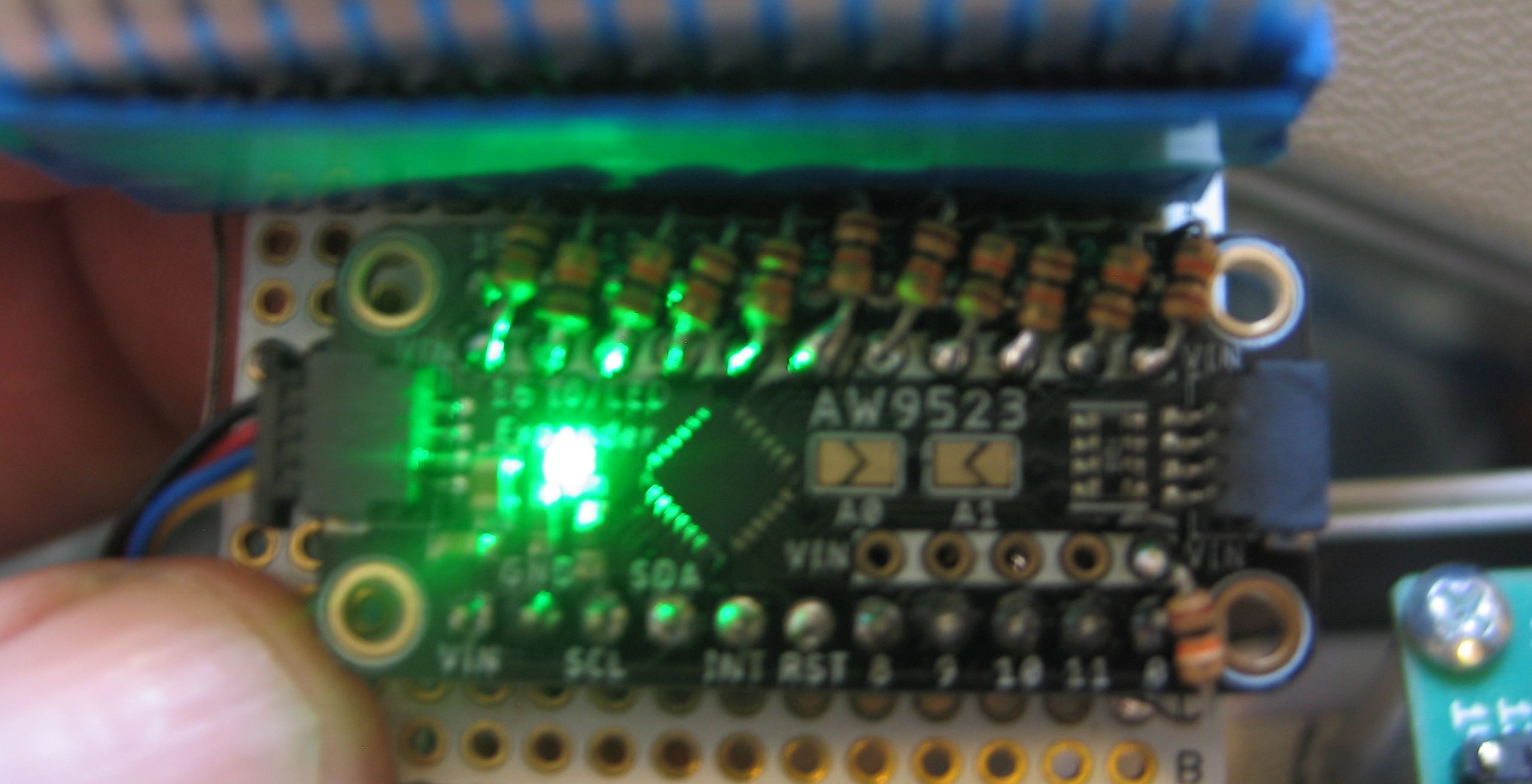
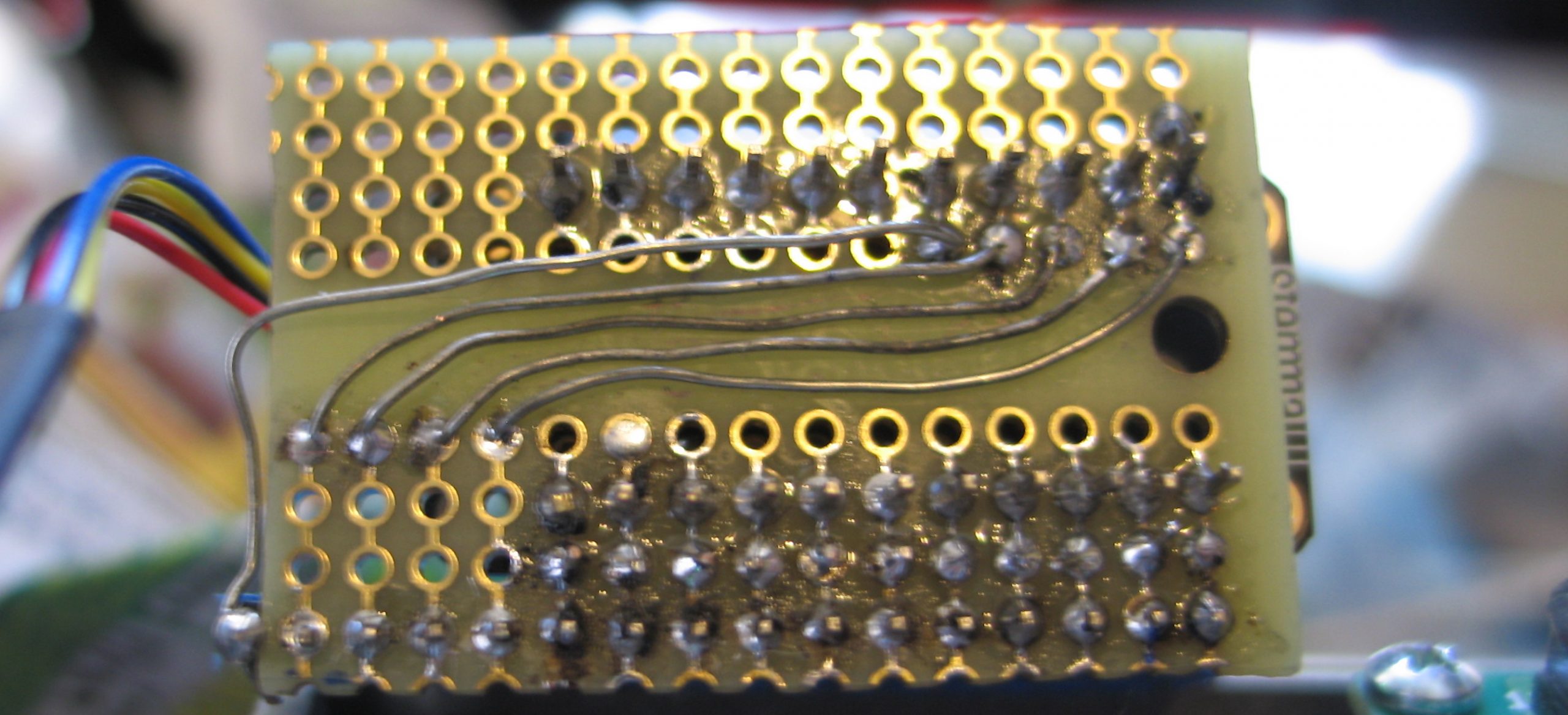
Of course for this to work we needed to solder 10k pull up resistors on all but the last 4 pins (8-11). This was relatively straightforward since there is a strip of connectors to VIN on the board. Still, kind of a pain. On the other hand I have reals of 10k resistors and I guess I have time.
Here is a simple circtuitpython program which presents a prompt and then puts characters scanned by the keyboard onto the display.
import time
import board
import busio
import adafruit_character_lcd.character_lcd_rgb_i2c as character_lcd
import adafruit_aw9523

keymap=[]
keymap.append('*# ZXCVBNM/\001')
keymap.append('-LASDFGHJK\r\n')
keymap.append('0912345678\010\002')
keymap.append('POQWERTYUI\030\004')

lcd_columns = 24
lcd_rows = 2
i2c = busio.I2C(board.SCL, board.SDA)
lcd = character_lcd.Character_LCD_RGB_I2C(i2c, lcd_columns, lcd_rows)
lcd.message = "PiTerm 1986 v0.0\nOk >"

aw = adafruit_aw9523.AW9523(i2c)
row_pins = [aw.get_pin(8),aw.get_pin(9),aw.get_pin(10),aw.get_pin(11)]
for pin in row_pins:
   pin.switch_to_output(value=True)

col_pins = [aw.get_pin(0),aw.get_pin(15),aw.get_pin(14),aw.get_pin(13),
            aw.get_pin(12),aw.get_pin(7),aw.get_pin(6),aw.get_pin(5),
            aw.get_pin(4),aw.get_pin(3),aw.get_pin(2),aw.get_pin(1)]

for pin in col_pins:
   pin.switch_to_input(value=True)


old_row=0;
for pin in row_pins:
    pin.value=1

switch_state = [[0,0,0,0,0,0,0,0,0,0,0,0],
                [0,0,0,0,0,0,0,0,0,0,0,0],
                [0,0,0,0,0,0,0,0,0,0,0,0],
                [0,0,0,0,0,0,0,0,0,0,0,0]
               ]
while True:
    for r in range(4):
        row_pins[old_row].value=1
        row_pins[r].value=0
        old_row=r
        for c in range(12):
            if (col_pins[c].value==0 and switch_state[r][c]==0):
                switch_state[r][c]=1
                print(keymap[r][c])
                lcd.message+=keymap[r][c]
            if (col_pins[c].value==1 and switch_state[r][c]==1):
                switch_state[r][c]=0
    time.sleep(0.01)  # debounce