Note: This work is ongoing see the Benito info page for current info…

Introduction.
The Benito Board is an at90USB162 board intended for use in programming and communicating with microcontrollers which have serial based bootloaders.
Among those are the Phillips lpc21xx series ARM chips, the Dallas Semiconductor, DS500x family and Atmels using any number of STK500 compatible bootloaders.
In the case of the Atmel and Phillips chips, a reset pulse is required to put the device into programming mode. A logical trigger for this pulse is the DTR signal which is pulled low when the computer begins to talk to a given device.
Background
Recently on avrfreaks.net….
Smileymicros wrote:
Now that they have the AT90USB82 for $2,17 each per hundred at DigiKey, I’m forced to reconsider. Why the f*ck would I continue using the FTDI part which costs $3.89 each per hundred?Smiley
It was not the first time I had had this question posed. Paul Stoffregen was talking about the new at90usb82/162 a few months back; its cheaper than the ftdi232 and has at least 2 driverless public usb-serial implementations: Dean Camera’s and Atmel’s. The best part is that it has a built in usb based bootloader and its a fully programmable AVR microcontroller. I thought it would be perfect to replace the ftdi ft232 series chips and to build an stk500 programmer with built in usb to boot. It seemed like the thing to do for many reasons.
Hardware
The sample code from both Atmel and MyUSB are based mostly on the AT90USBKey so I started with the schematic from that and cut out everything that I didn’t need. (a careful rereading of the datasheet says I am missing a 1uf cap here can you find it?).
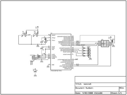
Compared to the the ftdi boards I have been working on the parts count is pretty high but I am banking on flexibility to make it worth while.
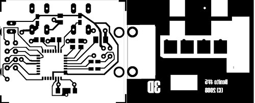
Click for link to positive at 600%
For the prototype I used my usual 1.5 sided board technique where the ground plain is brought to the top of the board and the alignment can be off by a couple of mm. The leds are some super bright ones in a plcc4 package that I have several hundred of. The pads in the eagle library for them are HUGE. I turned over the eagle files to Monty Goodson of bittybot.com who has lots of experience at getting things to be small so hopefully the final board will be a lot smaller.
In the mean time feel free to use the Positive image above to create your own board
The Programming Header

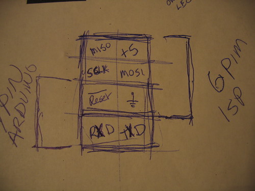
At the moment I have a very AVR centric view of the universe. For that reason the programming header that made the most sense was a combination of a serial connection with the 6 pin isp connection. For target boards based on other processors such as the DS5000 and the LP21xxx the SPI pins can be repurposed and the software adjusted accordingly.
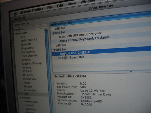
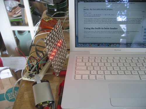
Using the built-in boot-loader
When you get power, usb, crystal, reset and hwb wired you can enter the chips usb boot-loader by holding HWB low during reset. If you have a mac like me and look look at the usb section of your system profiler you should see the following:
device AT90USB162
DFU:Version:    0.00
Bus Power (mA):    500
Speed:    Up to 12 Mb/sec
Manufacturer:    ATMEL
Product ID:    0x2ffa
Serial Number:    1.0.5
Vendor ID:    0x03eb
You can now program the chip using Atmel’s FLIP utility if you are running windblows (sic) or Weston T. Schmidt’s dfu-programmer on sourceforge http://dfu-programmer.sourceforge.net/ DFU stands for Device Firmware Update.
Running dfu-programmer looks like this.
$ dfu-programmer at90usb162 erase
$ dfu-programmer at90usb162 flash --debug 20 USBtoSerial.a90

target: at90usb162
chip_id: 0x2ffa
vendor_id: 0x03eb
command: flash
quiet: false
debug: 20
device_type: AVR
------ command specific below ------
validate: true
hex file: USBtoSerial.a90
Validating...3182 bytes used (25.90%)

$ dfu-programmer at90usb162 start
I made the .a90 file from my modifications to Dean Camera’s sample code (to be described later) with the following voodoo.
avr-objcopy -R .eeprom -O ihex USBtoSerial.elf USBtoSerial.a90
Now on top of the blinking lights on the board an entirely different device is attatched to my usb port.
The “Driverless” Serial Device.
The USB standard is a lot about throwing several thousand dollars down so you can play as a member. Fortunately for the rest of us there are a couple of generalized devices that have generic definitions. one is the HID (human interface device) and the other is a CDC communications device under the CDC a class of devices is defined which looks like a modem (ACM). If a device says its one of these and acts accordingly most well developed operating systems will load a generic driver for them and just work. (and then there is windows which still requires a .inf file to load the generic driver).
Atmel’s Code Samples.
As much as I love Atmel’s processors it is a constant source of irritation that their best tools are only made available on the windows operating system. It was nice to see that the sample code for Atmel was available for avr-gcc and I ran it up only to find myself picking through 5 layers of slashes “”. This is not just a preference, it is bad coding. (to quote an old co-worker of mine “Its Rubbish — Bin it!)
So I ran it up made it work and started looking at alternatives.
This lead me to Dean Camera’s MyUSB library. Though it is still in development it is much easier to understand and work with than Atmel’s Code.
crtusb162.o
When compiling Atmel’s CDC code I wound up with a linker error complaining that crtusb162.o did not exist After recommending AVRMackPack for nearly 6 months I thought I had found my first bug. After rebuilding my own version of the tool chain and digging around I found that it is a known bug and should be fixed in future releases. In the mean time the fix is easy. Either copy it from the avr3 directory into your source or link the avr3 directory to avr35 where the linker should find it.
#cd  /usr/local/AVRMacPack/avr-4/lib/
#ln -s avr3 avr35
Building the Firmware with MyUSB
The firmware linked below under resources implements a USB serial port which produces a 2ms *reset pulse instead of DTR. It is based on the USBtoSerial Demo from version 1.3.2 of the MyUSB library. To build it unpack the MyUSB library into your work area. Then under the MyUSB library directory create a directory called Projects and unpack the Benito firmware into the Projects directory. If you have xcode (v>2.4) and AvrMacPack you can open the project and build it. Other platforms will have to adjust the Makefile to match their environment. the “make program” target defined in the make file uses the dfu-programmer utility so you can program the device using its built in boot-loader.
Results:
By using Dean Camera’s MyUSB library I was able to create a serial programmer which plugs into Linux and OSX and it “just works”. I was then able to produce the reset pulse in firmware and it continued to “Just Work”. You can see it above plugged into a modern device RBBA board running Limor Fried’s AdaBoot. I was able to do this in a very short amount of time and while the hardware is slightly more complicated than the ft232 boards the cost at 100 boards is actually cheaper.
Moving Forward
In the photo below you can see my prototype board (both sides) next to an ft232rl based programmer with a .1uf capacitor “auto reset hack”. The board on the bottom shows a programming connection between an at90USB82 and a phillips Arm chip.

On the Atmel side the next step is to implement an STK500 based programmer using the SPI port on the at90USB162. I expect that this will be a fairly easy adaptation however first I may revisit the DS500x chips that I have and figure out the best way to switch between the programming and communication modes. From there it would also be a no brainer to adapt the firmware for the lpc21xx chip pictured above.
paul
You should really locate C3 right next to pins 3 and 4, with direct, short traces. There’s really no reason not to, since there’s plenty of room under the crystal. Or better yet, put another capacitor there. The value doesn’t matter, 0.01 uF with short traces is a LOT more effective that 1 uF on the other side of the board.
Virtually all the current consumed by the chip is via those two pins, and it’s all high speed current pulses. Locating the cap on the other side of the board makes all that high frequency current travel though a pretty horrific loop since the Vdd trace runs around the right edge of the board and the primary ground return is back up and slightly to the left (on the top side).
Atmel recommends a 10uF capacitance capacitor on the Vbus line (section 19.3.3, Design Guidelines, page 187). That’s mainly because of worry over poor power quality from the PC and the high voltage spike during dynamic disconnect (due to current still flowing in the inductive lines inside the USB cable). The FTDI chip suggests a series inductor, which is great for protecting your device against the spike, but totally goes against the letter and spirit of the USB spec, where both host and device and supposed to put low ESL capacitance on the bus to share the burden of suppressing that spike.
Single layer boards are difficult, and it’s pretty impressive you got it all on there. Sometimes it’s just not possible to do good decoupling on a single layer board, but in this case (assuming you’re only going to use 1 cap), you can easily put it right next to pins 3 & 4 where it will do the most good.
ax
I am running Ubuntu, I installed the Ubuntu packages for binutils-avr and gcc-avr but had to install avr-libc from source because (at least at this time) Ubuntu doesn’t have a package for avr-libc-1.6.2. I installed avr-libc-1.6.2 with prefix /usr/ because I couldn’t figure out how to use it from /usr/local/.
I did run into the problem where the linker doesn’t find crtusb162.o, but on my platform it is looking in avr5/
so what I did was:
cd /usr/avr/lib/avr5/
sudo ln -s ../avr3/crtusb162.o
Then the Benito software will build (though my version of avr-size does not take the option –mcu=at90usb162, so I had to change it from:
ELFSIZE = $(SIZE) –mcu=$(MCU) –format=avr $(TARGET).elf
to:
ELFSIZE = $(SIZE) –target=elf32-avr $(TARGET).elf
Is this even correct?
Alternatively (with out having to use sudo) you could do:
avr-gcc -dumpspecs > /tmp/specs
then substitute:
mmcu=at90usb162 mmcu=avr5
with:
mmcu=at90usb162 mmcu=avr3
(I use vim :%s/mmcu=at90usb162 mmcu=avr5/mmcu=at90usb162 mmcu=avr3)
Then edit the CC target in your Makefile to be
CC = avr-gcc -specs=/tmp/specs
Then you should be able to build.
(maybe you could put it in a better place and use it again later)
Anyways, with these two methods I was able to install the benito firmware onto my device (sudo make program). Then I did:
cat /dev/urandom > /dev/ttyACM0
and the light lights up!
apollo21
I have “AT90USB162” and “AT90USB647”.
I want to use “AT90USB162” for “ISP” and “JTAG”.
I want to use “AT90USB647” for “Dragon”, but do you have the document?
How do you write in those firm ware?
[[Image:A test board|left|100x75px|]]
apollo21
As for Schematic which I watched, “Benito board rev 5” frequency is not clear.
I supposed it to be “8MHz”.
I have holdings of “only “12MHZ” and 16MHz” unfortunately.
I intended I exchanged frequency in “Avrstudio4”, and to compile it, but was not able to find the method.
I want “five Benito board rev Firmware_12MHz”.
Is it difficult?
apollo21
I confirmed that AT90USB162 worked in “8MHZ” and “16MHZ” and “12MHZ” did not work.
I supposed that the voltage was right in reading it not having JTAG and HVPP, the voltage of HVSP that I made the trial of the pin arrangement and applied a pin arrangement as follows.
I can use 2-pin elsewhere when I use an oscillator in substitution for a crystal.[[Image:New pin arrangement|left|87x100px|]]
apollo21
Furthermore, a signal turned over and shared “RST_CTL” with “SS_RST”, and “RST_HZ_CTL reversed a signal, too” and saved Schematic and put up speed more.
[[Image:A voltage control circuit.|left|100x63px|]]
feurig
Because the chips built in dfu will work with 8 and 16, and I thought I read somewhere that 12 would work but I haven’t tested that.
mrbatu
I’m unable to download the project files including the at90usb.lbr eagle library. Is there someone who can help and send me this file?
Thanks in advance.
feurig
After some experimentation and realizing that my 3 v circuit didnt work I found that I had better results with a 16mhz crystal. All benitos built out by me since november have 16mhz crystals.
feurig
I recently added a teensy++ entry and also a part for the 32u4 so I will reupload them shortly.