(this is part of an ongoing DorkbotPDX workshop series being sponsored by TempusDictum, Inc.)
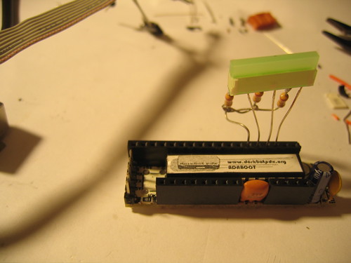
A few weeks ago I bought the last of the Really Bare Bones Arduino rev A boards from Brian at Wulfden (http://wulfden.org/freeduino/freeduino.shtml) I now have enough boards for one more workshop and then we have to reevaluate the boards which are avaliable. Pictured below is a finished board from the first “Arduino Cult Induction Workshop”
In addition to letting me clean out his new old stock Brian threw in one of the “Rev B” boards so I could check it out. Unfortunately I don’t like it.

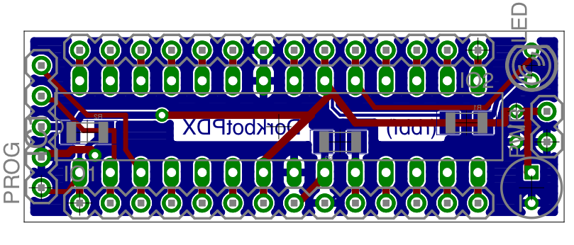
The new board is almost 3/4″ of an inch longer than the original. Most of the new space is dedicated to room for a power jack and a regulator. Things that I never use. The design is supposed to allow you to cut the power jack off as well as the regulator. Notice in the finished board above that their is space for a big old reset switch. When the original Arduino came out you had to reset the board to get it into the bootloader. However in the past year or so all the new boards have been using the dtr signal run through a capacitor to pull the reset line so the switch is wasted space. The original board made up for this space by adding ample ground and supply connections. The new board adds another 1/8″ and gets rid of these.
As I was grumbling about this Mark Gross suggested that I just roll my own.
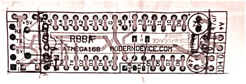
So we are back to the drawing board. Above is my pen markup of the changes that I wanted to see done to the original Really Bare Bones Arduino and below is the draft of the rework to scale with the RBBB rev B.
Now comes the fun part (not) The cost of goods sold and a business case.
paulb
Hey good work with this. Smaller and cheaper are always winning ideas with me. You may easily have achieved the smallest possible DIP implementation of a Freeduino. I especially like your comparison (perhaps) implying that feature bloat eventually ruins every design, or the RBBB now approaches the size of a cruise ship.
Some small suggestions.
Looking at the board layout above, it looks like you snipped out the reset switch. This is OK although it eliminates handy resets – although a piece of wire from the reset pin would do as well – sometimes a useful thing, to restart the program aside from download.
You might want to think about putting the sixth cable pin and reset cap back in (plenty of room under there if you’re going to surface mount – since it would facilitate going to the Diecimila bootloader, which is a little faster on some (Windows) machines. As much as I like Adaboot, it doesn’t kill all the wait states on certain Windows machines. For those who are affected (or afflicted) Diecimila does end up saving a lot of time over a long development process, and would involve only minor change in your board. It also is going to facilitate lack of the reset switch, since having to either hook up a switch or mess with a piece of wire on each program download seems like a fuss.
Another thing to think about is the addition of a Ground and 5V pins near reset and RX TX pins, to facilitate people who wish to use our P4 RS232 programming adapter or something similar. There seems to be a diehard group of RS232 fans out there who like that option. Also it’s cheaper than the cable. We are proposing the pin order of the P4/RBBB as a standard (RST, G, 5V, RX, TX) but suit yourselves (the P4 is easily remapped for other configs). Of course I know adding a pin here, a pin there, you’re up to the Queen Mary in no time.
It is also true that the P4 (or similar) could easily be remapped to work with the cable headers.
The one meg resonator load resistor turns out to be unnecessary and you can eliminate that entirely – it’s built into the atmega circuitry.
On another note, I still have 30 or so of the Rev A boards that you’re such big fans of, and know whether another 100 possibly are squirreled away, send me some email if you want them.
Paul Badger moderndevice.com
feurig
Paul,
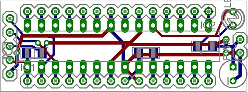
I am a proponent of moving the reset pulse onto the programmer. Either with a cap (like this design from sparkfun — http://www.sparkfun.com/commerce/product_info.php?products_id=8551), or in firmware (like my own design (http://www.dorkbotpdx.org/blog/feurig/benito_7_the_next_big_thing). My experience has been that if you do want the reset you will want it on the outside of the enclosure and not on the board. So in this board it is brought out twice once next to the pin and once on the programming header. The new pinouts were not as easy to get into the board as I thought given the profile and the need to have the clearances required by our local board fab (www.sunstone.com) but the rev I am going to roll with incorporates your proposal in stead of maintaining pin compatibility with the rbba.
So I do hope you are serious about this change. Thank you for the solid and constructive feedback.
Don.