Note: This work is ongoing see the Benito info page for current info…
Introduction
This is a first take on using the Benito board to create an open source USB to Serial converter.
Benito 7b Buildout from Donald Delmar Davis on Vimeo.
The above video was assembled from photos taken by my son Aidan Davis. The entire set is on flikr at http://www.flickr.com/photos/7175086@N05/sets/72157606639780833/
The benito board was designed to allow people with intermediate soldering skills to build their own Atmel AT90usb162 based devices. The processor itself is a tqfp and the remaining components are almost exclusively smd 806 parts. While it is not as easy as working with dip components, it is not too difficult to do by hand and the processor is worth it.
Hardware
| PARTS (Digikey, most smd components in 806 package) | ||||
|---|---|---|---|---|
| # | Digikey # | Description | Price(@1) | Price(@25) |
| 2 | 475-2560-1-ND | LEDs | 0.14 | 0.12 |
| 1 | AT90USB162 | usb chip | 3.76 | 3.15 |
| 2 | RHM10KARCT-ND | 10k resistors | 0.04 | 0.03 |
| 2 | RHM220ACT-ND | 220 ohm resitors | 0.14 | 0.08 |
| 2 | RHM22ACT-ND | 22ohm resistors | 0.16 | 0.08 |
| 1 | 631-1099-ND | 8 Mhz xtal | 0.5 | 0.5 |
| 1 | 399-1168-1-ND | .1uf cap | 0.05 | 0.03 |
| 1 | 399-1284-1-ND | 1uf cap | 0.1 | 0.06 |
| 2 | PCC220CNCT-ND | 22pf cap | 0.44 | 0.44 |
| 1 | PCC2232CT-ND | 4.7uf cap | 0.33 | 0.33 |
| 1 | 609-1039-ND | USB conn | 1.03 | 0.55 |
| Benito Board http://tempusdictum.com/tdproducts.html | ||||
| 1 | Benito7g | Benito Board | 4 | 1.6 |
| 10.69 | 6.97 | |||
Schematic
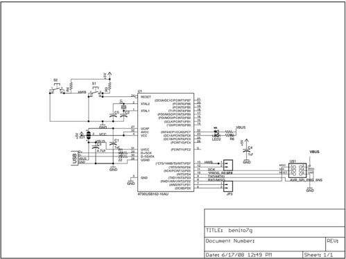
Schematic: click for a Larger View
(larger size : http://www.flickr.com/photos/7175086@N05/2693613068/sizes/o/)
Parts Layout
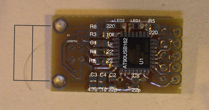
The above lays out the surface mount components on the top of the board. There is also a 10K resistor on the other side of the board.
Software
The firmware is attached in both source and
precompiled binaries.
To build it from source you will need an avr-gcc toolchain such a:
- AvrMacPack (OSX)
http://www.obdev.at/products/avrmacpack/download-de.html - WinAVR (Windows)
http://winavr.sourceforge.net/ - Or you can build your own (linux)
http://www.avrfreaks.net/index.php?name=PNphpBB2&file=viewtopic&t=42631
The software was written using Dean Camera’s MyUSB library.
The at90USB162 has a built in bootloader and it shows up as an AT90USB162 DFU. To use the bootloader you will need one of the following.
- DFU Programmer (Linux/OSX)
http://dfu-programmer.sourceforge.net/
Which requires libusb(http://libusb.wiki.sourceforge.net/) - Atmel’s FLIP utility (Windows and Linux)
http://www.atmel.com/dyn/products/tools_card.asp?tool_id=3886
Populating the board
Tools:
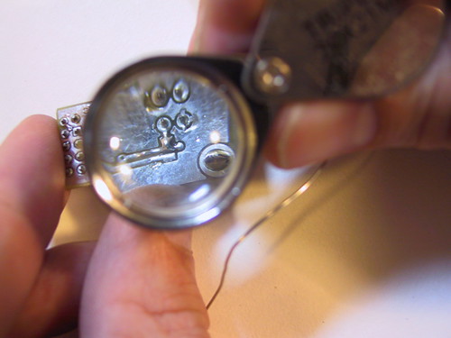
I use a 25 watt weller pencil type iron and i usually sharpen the tip with either a file or a dremel cutting disk. you will want to have the smallest diameter solder you have and some solder wick handy. Since I started doing surface mount I have come to rely on a pair of 3x reading glasses from rite aid. I also have a magnifying glass that sunstone circuits sent me when I ordered these boards.
The Brains of the outfit.
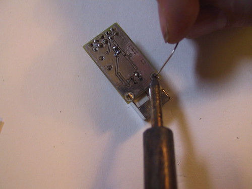
The first thing that needs to be done with the benito board is to align the processor on the board and tack the corners. I usually start with the vcc pin closest to the dot on the processor. There us usually enough tinning on the board to tack the pin in place without needing to add solder
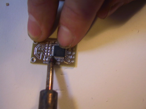
Then I tack the opposite corner fudging the pins to get the best alignment. Once this is done I walk around the pins touching each with the tip of the iron and touching the solder to the joint. If the solder blobs or creates bridges between pins dont worry too much. If its not looking like your getting a zen with it just blob it across all the pins and then clean it up using the solder wick. When you are done inspect your work.

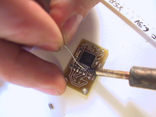
The Blinkin Lights.
I usually do the LEDs next most surface mount LEDs will have a green marking which goes on the negative side of the led. On these ones the mark was on the bottom but the dot in the center is off set towards the same end so you can still tell which is which. The negative side goes toward the pins on the processor. Bracketing the LEDs are the 220 ohm current limiting resistors. Solder these these on and check your work. If you get bridges don’t worry just draw off the excess solder as shown in the photo below.

Next up is the 10k pullup resistor for the reset pin and the 1uf capacitor which is used to create the 3.6v needed to communicate with the usb bus. In this build I only had a 603 size it is harder to work with but it fits on the pads just fine. Follow this with the 22 ohm resistors which help filter the D+ and D- usb signal lines.
The next two componets are the .1 bypass capacitor on the processor and the filter capacitor for the usb power. Atmel recommends a minimum of 1uf with a preference of 10uf. I usually split the difference and put a 4.7 here. In this particular build I only had a 10uf capacitor in a 1206 package.

The 1206 extends past the pad but we were able to solder it to the trace. The last two smt pads are for the 22pf capacitors that are part of the oscillator circuit. Solder these in place and get the 8 mhz crystal ready. Since the crystal sits above the caps and the pins on the side of the processor I usually put a piece of thick paper underneath it to keep it from making contact with anything.

Once the crystal is soldered in place, remove the paper and trim the crystals leads. Then solder the last 10k resistor onto the pads on the bottom of the board, install the 10 pin header, and the USB B connector.
The final step in assembling the benito is to select the voltage that the io will be using. If you are using your benito to talk to a 3-3.6v target you will short the outer jumper and the io portions of the chip will reference the internal 3.6v instead of the usb 5v supply. In this case we are talking to a 5v target and we short the jumper as shown below.
You are now ready to load the software onto your benito. There are pads on the bottom of the Benito for the hwb and reset switches. These are handy if you are going to be using the board for development but are not required. The pads were designed for a relatively expensive switch sold by sparkfun but my favorite switch in this spot is shown digikey part P8090SCT-ND.
Programming the Benito.
The AT90USB162 comes complete with a built in USB bootloader called the Device Firmware Uploader. When you plug your Benito in it will show up in your dmesg logs (on linux) or in your system profiler (for osx). The smoke test for your board will be to see if the DFU shows up when plug the device in. If there is a short it should trigger the overload protection on your usb port. On the macs this port will be powered down until you resolve the issue. If you are concerned about your system not handling this correctly you might consider a cheap hub. And always unplug the device if your system complains or if anything gets hot.
Uploading the firmware.
Assuming that no smoke left the device (jk) the benito should show up as an Atmel AT90USB162 DFU. (on OSX pull up the system profiler by going to “about this mac” in the apple menu and asking for more information. In the system profiler select USB and hit refresh (splat R). On linux type lsusb -v. If it complains that it cant see the descripters you may need to escalate privilages using sudo because DFU-Programmer needs to read them to identify the device.
When you unpack the source code you will find that the “make program” target calls dfu programmer to erase the chip, load the benito2g.a90 file, and reset the chip. If you are an x-code user the source tree includes a project file. Selecting the program target will call the “make program” target in the makefile. Refreshing the system profiler window on OSX or relisting the usb bus on linux should now show you a Benito7.
There will also be a new serial device! on OSX this will be /dev/tty.usbmodemXXXX and on linux /dev/tty.ACMX
Windows users will use the control panel to track the usb changes and will need to use Atmel’s FLIP utility to load the benito firmware. When the new device shows up it will ask for a driver open the Benito7.inf file in the source code folder. This will tell windows to use the drivers that it already has.