Motorboard Buildout. from Donald Delmar Davis on Vimeo
To build out the motorboards from the workshop requires placing and soldering the the two vias the H-Bridge driver, the capacitors and any connectors you want to use to connect the board to the motors and the Arduino or DorkBoard. The parts layout is below.
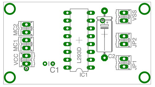
To connect the ground plane from the top of the board requires two “via”s or wires which can be cut from the tails of the capacitors in the kit. When I put these together I looped the capacitor tails through the holes. Also please note that the ground side of each capacitor is also acting as a via so solder both top an bottom on the leads as indicated by the arrows in the diagram below.

The center 4 pins on the chip serve as a “heat sink” which is one reason that there is so much copper left on the upper side of the board.
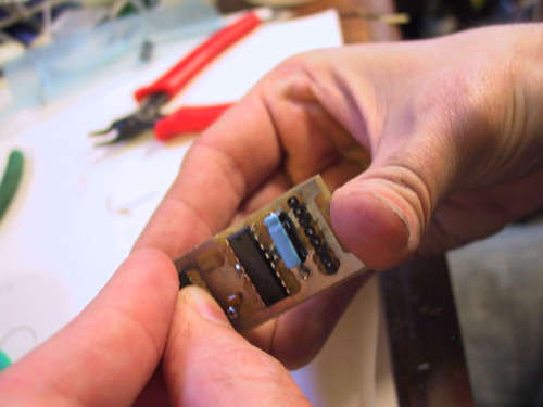
I connected a female header to the input side of the board so I could jumper the pins from my dorkboard and a Male header on the power end.
Using the motorboard is simple.
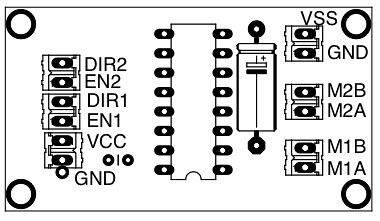
One end of the board connects to your arduino on the other end of the are the connections for the high voltage (4-35V) and the motors. The ENable pins turn the motors on and the DIRection pins determine the motor direction. If you use pins 9 and 10 for the en you can set the speed using the arduinos built in pwm as in the code below which was a modification of the “fading” example.
// Modified Fading Example for motor controll

int value = 0;                            // variable to keep the actual value
int motor1dir = 8;
int motor1pwm = 9;
int motor2dir = 11;
int motor2pwm = 10;

void setup()
{
  pinMode(motor1dir,OUTPUT);
  pinMode(motor1dir,OUTPUT);
  digitalWrite(motor1dir, HIGH);
  digitalWrite(motor2dir, LOW);
}

void loop()
{
  for(value = 0 ; value <= 255; value+=5) // fade in (from min to max)
  {
    analogWrite(motor1pwm, value);           // sets the value (range from 0 to 255)
    delay(30);                            // waits for 30 milli seconds to see the dimming effect
  }
  for(value = 255; value >=0; value-=5)   // fade out (from max to min)
  {
    analogWrite(motor1pwm, value);
    delay(30);
  }
  for(value = 0 ; value <= 255; value+=5) // fade in (from min to max)
  {
    analogWrite(motor2pwm, value);           // sets the value (range from 0 to 255)
    delay(30);                            // waits for 30 milli seconds to see the dimming effect
  }
  for(value = 255; value >=0; value-=5)   // fade out (from max to min)
  {
    analogWrite(motor2pwm, value);
    delay(30);
  }
}