This is a snapshot of the current readme: Updates and current progress are on its github page: https://github.com/feurig/PiTerm1986
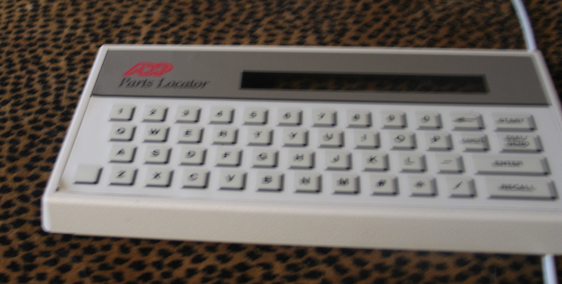
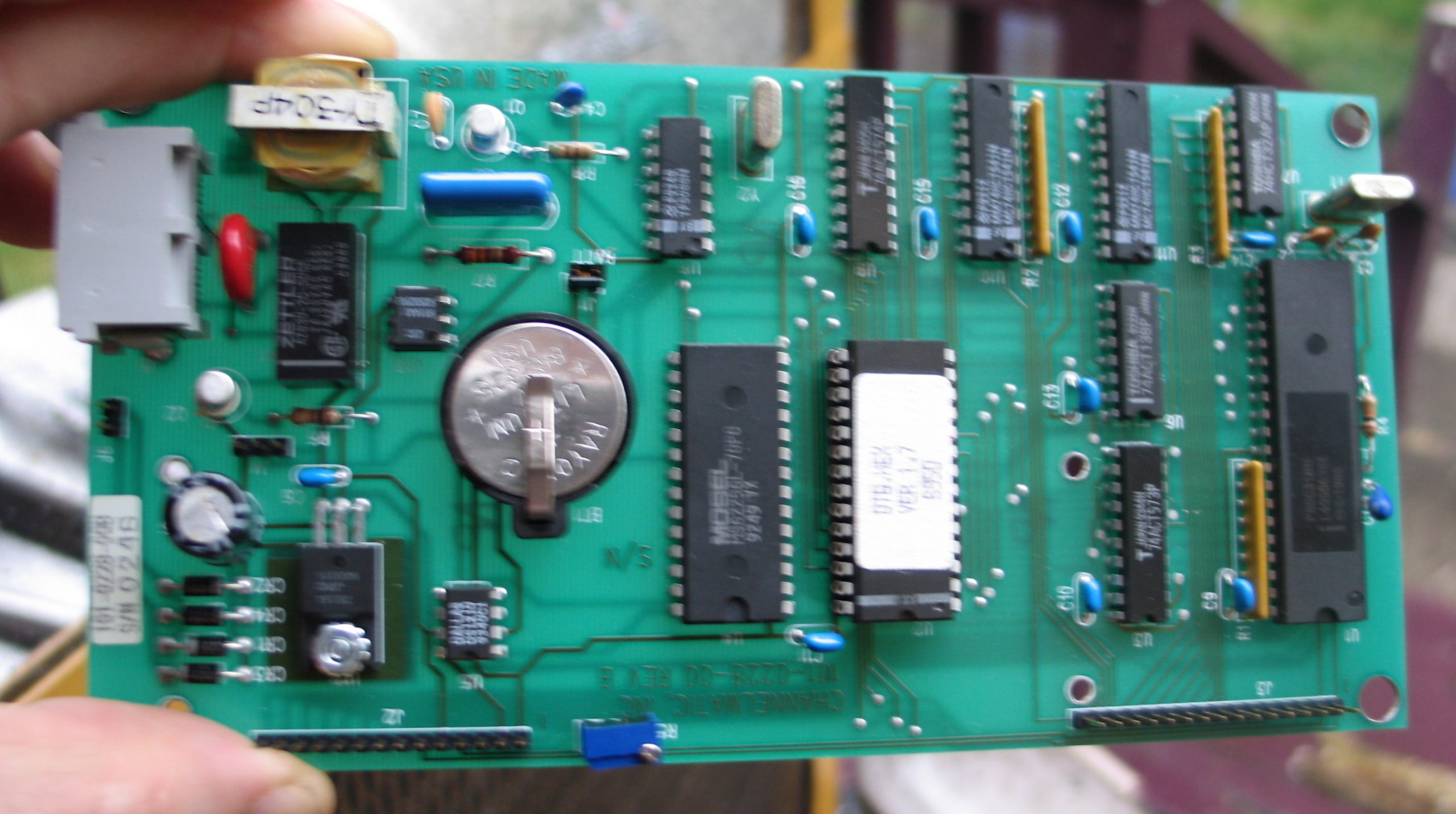
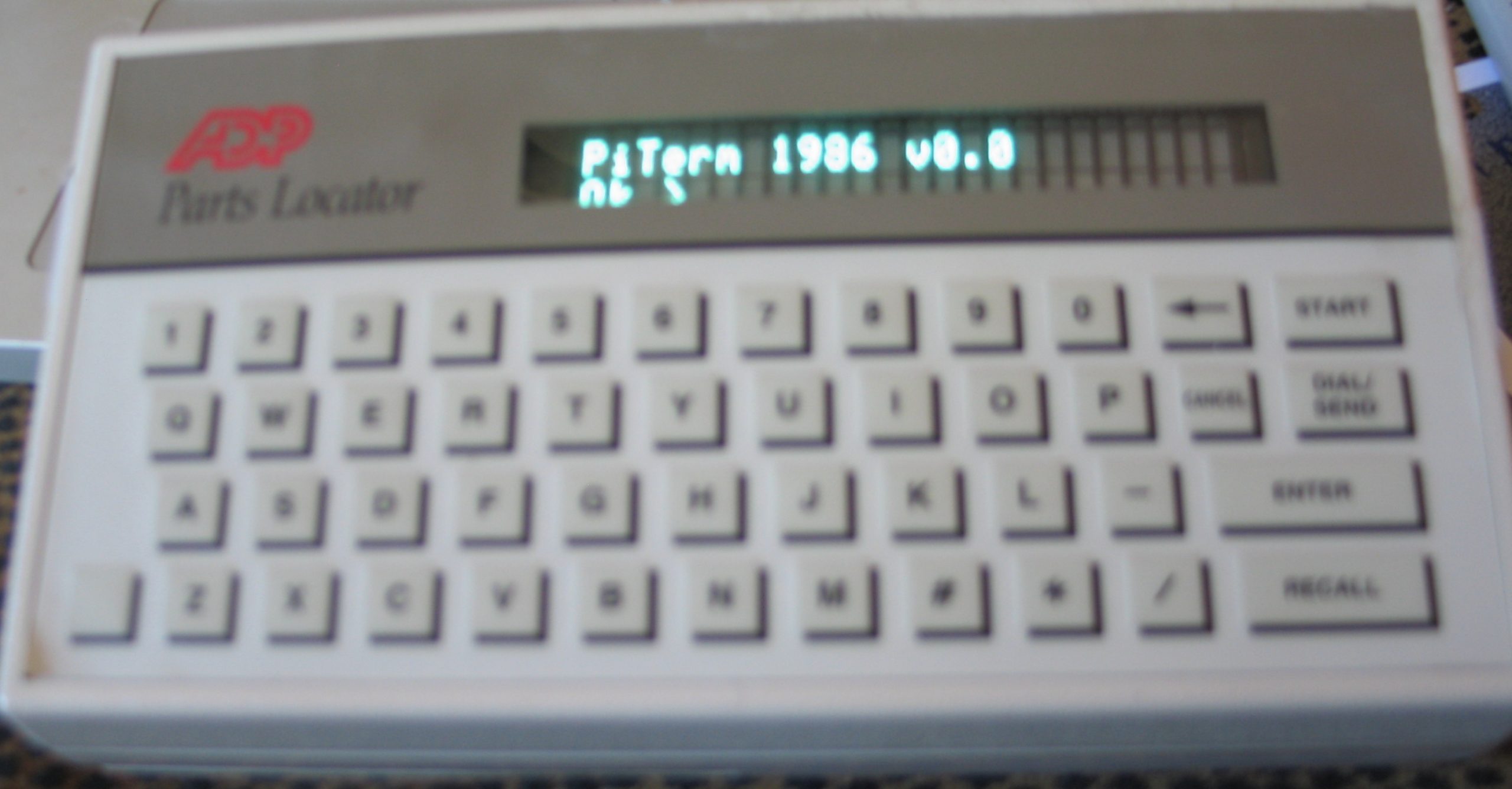
GOAL: Convert 80s style user interface ( 8031 based ADP Product: chicklet keyboard and 2×20 lcd ) to pi zero based terminal using i2c based io expanders.


Looking under the keyboard membrane and tracing the connectors we can get the following key map under a 4×12 array (16 pins).
   0123456789 10  11
   --------------------
0) *# ZXCVBNM/    <STOP>
1) -LASDFGHJK<N/C><ENTER>
2) 0912345678<BS> <START>
3) POQWERTYUI<CAN><DIAL>| * | # | Z | X | C | V | B | N | M | / | STOP | |
| – | L | A | S | D | F | G | H | J | K | N/C | ENTER |
| 0 | 9 | 1 | 2 | 3 | 4 | 5 | 6 | 7 | 8 | <—- | START |
| P | O | Q | W | E | R | T | Y | U | I | CANCEL | DIAL |
Keyboard
For this we look at the AW9523 GPIO expander with 16 pins of io.
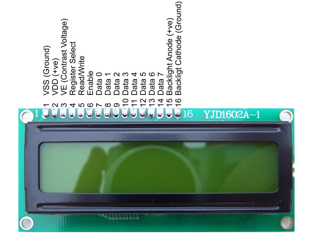
LCD/VFD
Since the LCD is a 5v circuit requiring either 8 or 12 pins we look at the Microchip MCP23017 on the Adafruit GPIO Expander Bonnet which we can wire either using both ports or one port in nibble mode.
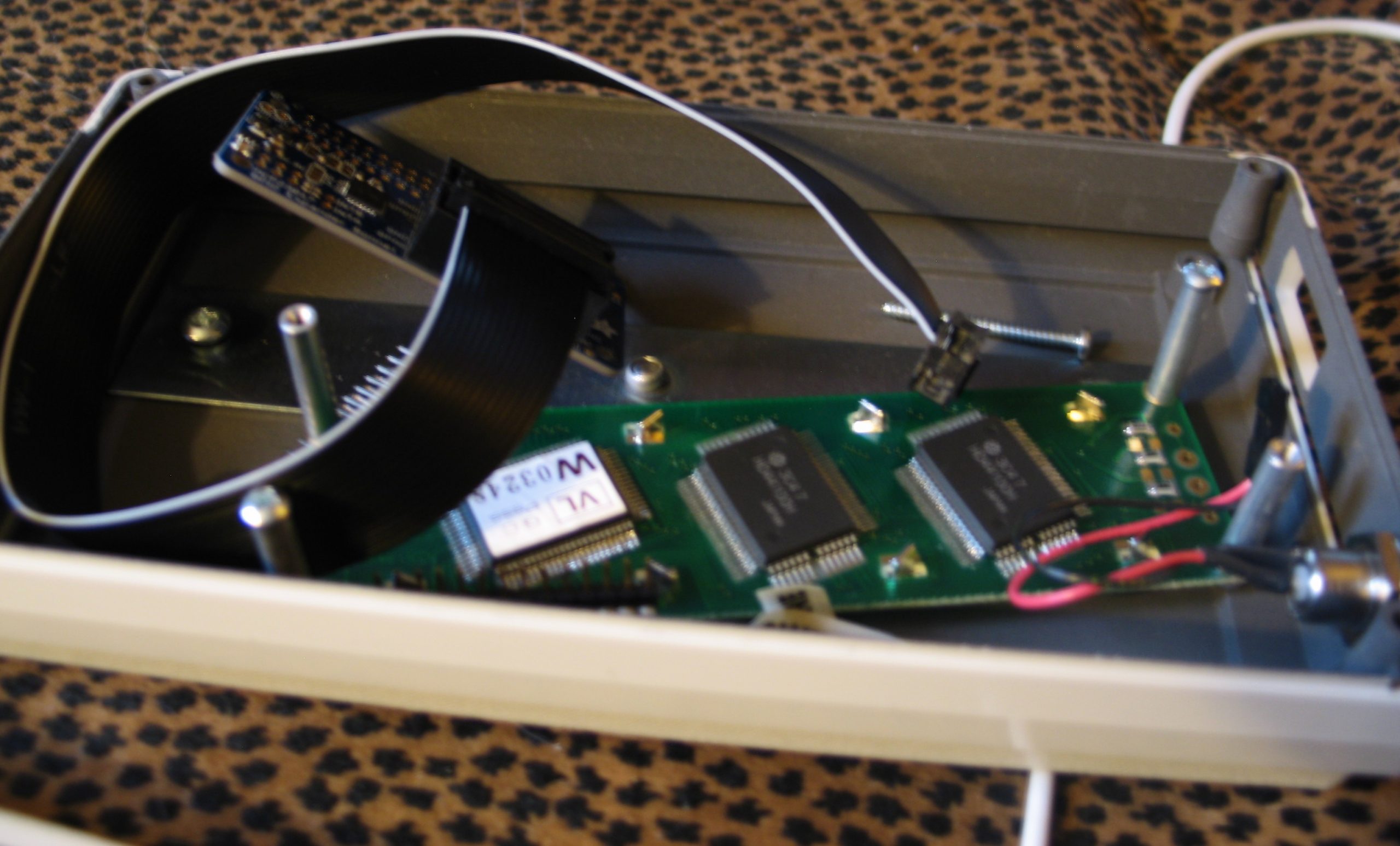
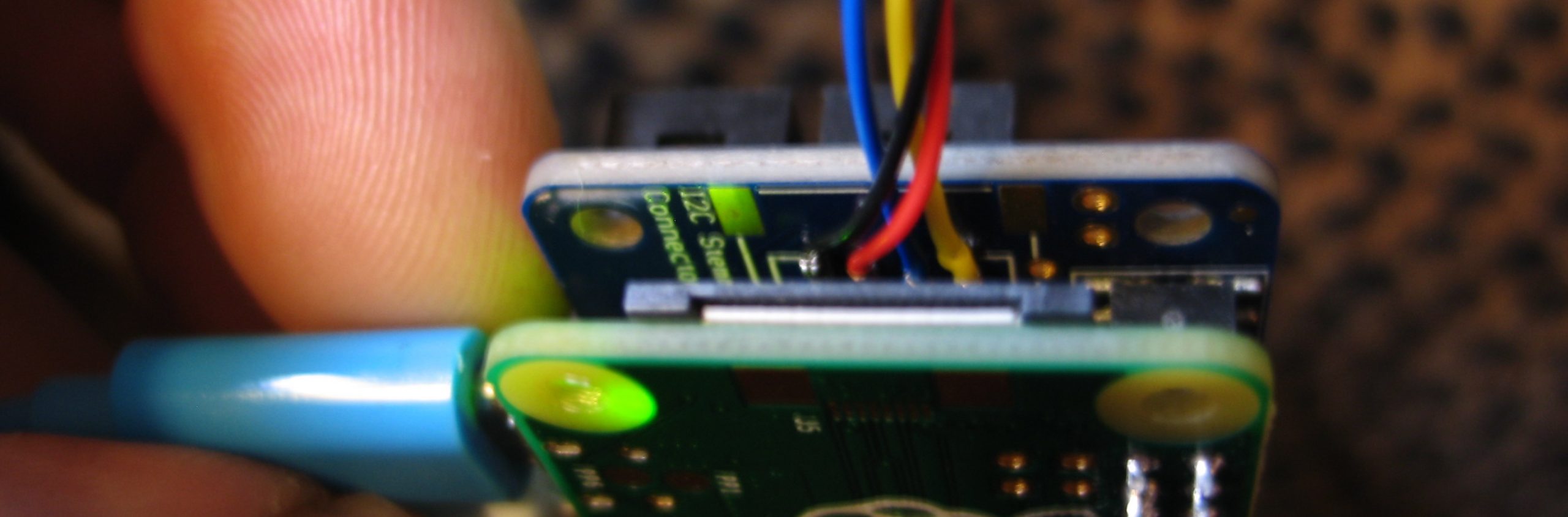
Attaching Both Boards to the Raspberry pi.

root@somepi1:/home/feurig# i2cdetect -y 1
0 1 2 3 4 5 6 7 8 9 a b c d e f
00: -- -- -- -- -- -- -- -- -- -- -- -- --
10: -- -- -- -- -- -- -- -- -- -- -- -- -- -- -- --
20: 20 -- -- -- -- -- -- -- -- -- -- -- -- -- -- --
30: -- -- -- -- -- -- -- -- -- -- -- -- -- -- -- --
40: -- -- -- -- -- -- -- -- -- -- -- -- -- -- -- --
50: -- -- -- -- -- -- -- -- 58 -- -- -- -- -- -- --
60: -- -- -- -- -- -- -- -- -- -- -- -- -- -- -- --
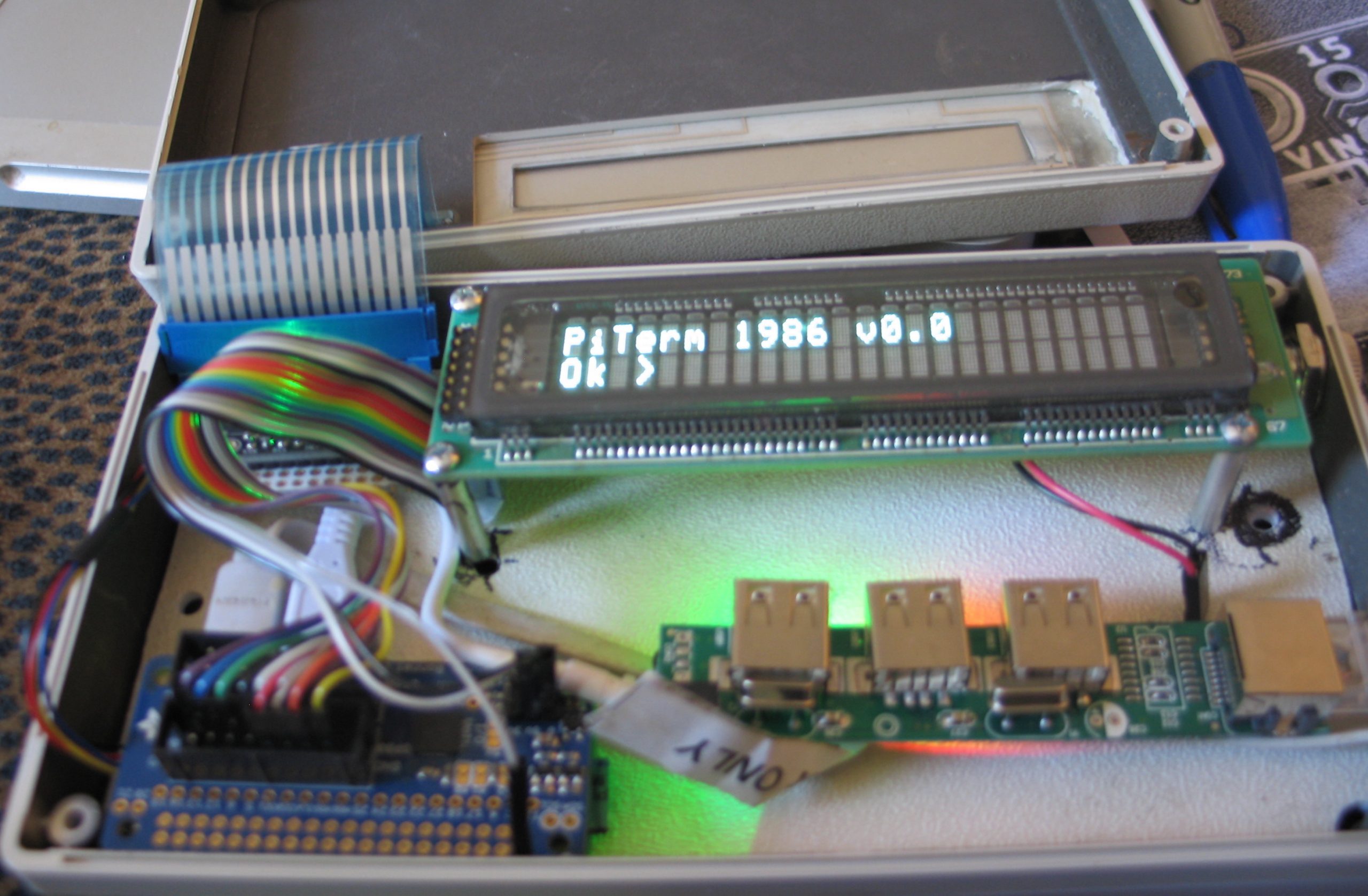
70: -- -- -- -- -- -- -- -- Assembly and layout.
After putting the board in the box I realized that the grey paint was conductive and that I almost let the smoke out of the pi zero. (you could smell it). So I went out and found a piece of plastic from a previous project.
And then I was like OH SHIT I have Noritake 2×24 VFD thats a close fit..
So there’s a circuitpython library for an mcp23017 connected to an lcd. Wiring it up according to the above schematic lets us write away
root@somepi1:/home/feurig# pip3 install adafruit-circuitpython-charlcd
...
root@somepi1:/home/feurig# python3
Type "help", "copyright", "credits" or "license" for more information.
>>> import board
>>> import busio
>>> import adafruit_character_lcd.character_lcd_rgb_i2c as character_lcd
>>> lcd_columns = 24
>>> lcd_rows = 2
>>> i2c = busio.I2C(board.SCL, board.SDA)
>>> lcd = character_lcd.Character_LCD_RGB_I2C(i2c, lcd_columns, lcd_rows)
>>> lcd.message = "Hello\nPiTerm1986"
>>> lcd.clear()
>>> lcd.message = "PiTerm 1986 v0.0\nOk >"
>>>
I am not thrilled about the way its wired but whatever.
References
- https://learn.adafruit.com/adafruit-aw9523-gpio-expander-and-led-driver
- AW9523 Datasheet
- https://learn.adafruit.com/gpio-expander-bonnet/overview
- MCP23017 Datasheet
- https://protostack.com.au/2010/03/character-lcd-displays-part-1/
- https://www.electronicsforu.com/technology-trends/learn-electronics/16×2-lcd-pinout-diagram