( this is a repost of http://blog.tempusdictum.com/index.php/don/uncategorized/reinventing-the-wheel-watcher)
Its not very often that you get to go back to old designs and make improvements. But when you do its nice. Recently I got to rework a design from last year and build on the collective knowlege of 2 design teams and 3 design cycles.
Does practice make perfect? We shall see.
The first run.
Last year I got to build the electronics for a stationary bike racing system. The system had a large ballfield style clock with four hands that were run by these monster stepper motors The initial design was for two bikes done by Percor: a company that makes excercize equipment. Their design used these industrial (expensive and very bulky) cherry hall effect sensors which they loaned us for a race at Lance Armstrong’s bike shop in Austin (http://www.mellowjohnnys.com/). My job for that cycle was to replace Percor’s pic based board with a 4 bike setup.

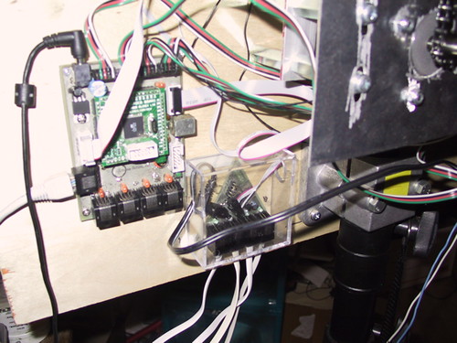
I broke the stepper driver section into four individual boards. For the processor I built a custom mega128 based board and did the programming in wiring.
Second iteration.
When the Austin race was over Percor needed their parts back so I got to rebuild the sensors. I found some allegra hall effect sensors which were a small fraction of the cost of the cherry’s (like (75c<$25.00)X4). As an attempt to get a zero indicator on the clock I experimented with a triangle based design 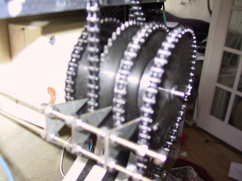
While I never did get this particular part of the clock to work correctly the triange stuck as a shape that I liked working with.

I also wanted to replace the cat5 wire used in the Percor design with with less expensive phone cord. (I got a panicked phone call from Texas and had to remotely direct someone how to get some very expensive ethernet cable on a weekend: it was not cool). To do this I put a non inverting buffer on the sensors and since buffers come in 6s I put an indicator led on the sensors output. In the practice of setting this up for the next race, the blinking lights were invaluable.
Third Time Charm.
A few weeks ago I was asked about another race setup in SanFrancisco. They were going to use a system called open sprints for the display but the open sprints people were out of their hardware for the sensors. So I got a 3 week timeline to put together a sensor and hardware interface that would be compatible with open sprints.
Open sprints (www.opensprints.org) is an open source ruby based software which takes information from an arduino and presents the race data in a way that can be projected instead of having a physical race clock. The only thing that needed to be built was the input side.
So I went back to what I liked and didn’t like about my earlier design and compared and contrasted the opensprints, the percor and my designs to come up with a new system which I could then have fabbed by our local pcb fab (sunstone.com). Looking at the opensprints design I revisited the hall effect sensors and found a set of sensors to experiment with and began to lay out my boards.
I had intended to use the dart design with a through hole led and a throuch hole (sip) sensor and then have some laser cut transparent plastic which could then be “lit” up by the led on the board. A second piece of opaque plastic would be cut to insulate the bottom of the board.
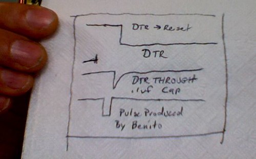
After talking to some of my ee freinds I decided to replace the on board drivers with a single schmidt trigger on the other end of the sensor cable (the percor design used these as well) When selecting the parts I found myself looking at a few options for the rj11 connectors. I ordered a few of each as well as both sip and the origional smt sensor from last year.
Who needs plastic?
When I got the parts I started looking at these rj11 connectors and rethinking things. The connectors were surface mount and shielded. The shielding wasn’t needed but they matched the un-soldermasked boards in texture in color they were about 7 cents more expensive apiece but they looked futuristic.
I went back to surface mount only. If I got rid of the sips and used the surface mount rj11 mounts then the bottom of the board would be shield/ground no insulation needed. The metal from the surface of the board and cable connector would reflect the light from the led and if any attention were payed to the layout of the traces it would look cool!

Even in the hand rolled prototype!
Who needs an Arduino?
At this point given Paul Stoffregon’s (pjrc.com) “teensyduino” software and his 90usb based boards there is no reason to buy any other arduino or arduino clone. ( at least in cases where you need usb to serial solution — in cases where usb-serial is not needed the dorkboard rules :) My first thought was to do a carrier board for on of Paul’s boards and adapt the opensprints code for the inverted inputs. The opensprints code needs to be adapted to invert the input signal and to adjust the registers for the different processor but using the teensyquino codebase that should be simple enough.
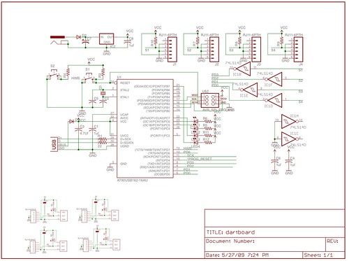
In this application however, the board was so simple that it made more sense to just adopt the eagle design for my at90usb162 board (the benito).
Tomorrow I get the boards from sunstone and I should have the hardware built out by late friday. The customer will be in portland saturday.
Does practice make perfect? We will let you know by next week.


 Wax Teeth
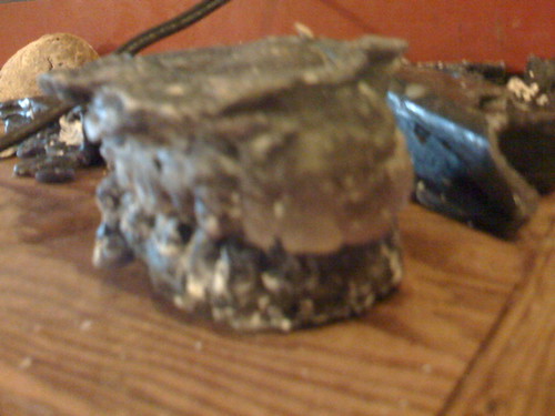
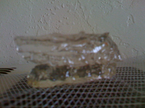 Resin Teeth
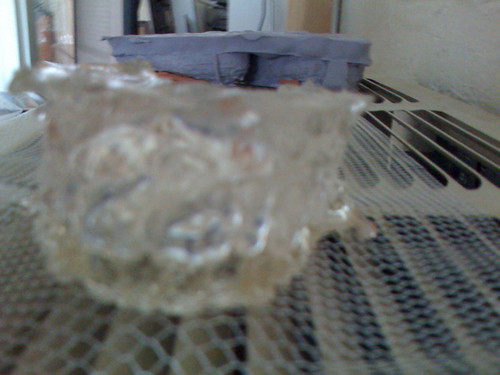 Resin Teeth with new clay drying in the background.