by on electronicsOpenWrt

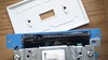
Most of this week has been devoted to finishing the house network setting up a workspace in the garage and using it. One of the things I have been trying to get off of my plate was to rebuild the transit tracker that we use to tell us when the next max is going downtown. In order to network from the house to the garage I have to navigate a super creepy crawl space and not get spider bitten or set up a wireless bridge. One of the OpwnWrt devices we bought to evaluate seemed perfect. The TP-Link TP-WR740.


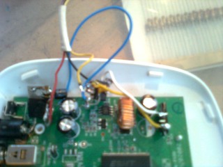
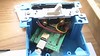
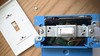
Getting the OpenWrt operating system on the router is pretty much a matter of uploading the new firmare ( http://downloads.openwrt.org/attitude_adjustment/12.09-beta/ar71xx/generic/openwrt-ar71xx-generic-tl-wr740n-v4-squashfs-factory.bin) using the routers web based interface. Accessing the serial port required some surgery.


Once the serial was connected to the 4 pin connector I tested it with my ftdi.3.3v serial cable. Then I tried to see if the 3.3v tx signal was strong enough to be read by a sparkfun 5v serial lcd board I had on the bench. It wasn’t. If i had the parts for the 3.3v-5v boards i had fabbed last month (in particular the 74ahc125) then I would be done. So I looked around for what I could find. One of the documents I found on this was an app note from microchip called “3V Tips and Tricks” (http://ww1.microchip.com/downloads/en/DeviceDoc/chapter%208.pdf). As I was looking through it I went out to the garage and tried to see what I had that I could use. In a box labeled “chips and dips” I found a bunch of lm393 comparators that I had been packing around for over 10 years.

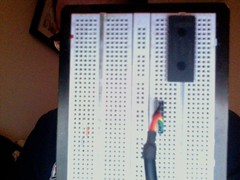
So I soldered an lm7805 to the dc coming in and the ground-plain started breadboarding.

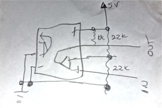
I got no love from the resistor values provided by microchip so I put a pot in place opened a minicom connection to the serial on the router, held my hand on the g key, and rotated the pot until I got ggg’s on the lcd. Then I continued until I stopped getting characters. Then I centered the pot in between those places pulled it out and measured it with a multimeter. Which gave me the circuit below which I wired up bug style and embedded in hot glue.


There was still a little work to do. The OpenWrt luci system takes up a lot of space but makes trying things very easy. The command line tools aren’t bad but luci comes with most of the stock images which is ok. The thing that forced me to build a custom image was that the fact that the serial port starts up at 115200 baud rate and my lcd module didn’t support that. To make matters worse sending the boot messeges at 115200 created serial sequences that would corrupt the lcd module.

To get the baud rate to 9600 required me to:

  • Upload the OpenWrt-ImageBuilder-ar71xx_generic-for-linux-i486.tar.bz2 to one of my linux machines.
  • Find and replace parts of the Makefile where the console baud rate was hard coded. (target/linux/ar71xx/image/Makefile)
  • “make image” with the correct target and any packages I wanted installed.

I also commented out the install luci part in the .config file at the top of the tree and added the trimet.lua script to a /scripts directory and which was magically added to my custom image (though not were I expected it to be).

make image PROFILE=TLWR740 PACKAGES="nano coreutils-stty coreutils-nohup monit lua luasocket" FILES="myscripts"

This created several images including one called bin/ar71xx/openwrt-ar71xx-generic-tl-wr740n-v4-squashfs-sysupgrade.bin
to install it i scp’d it to the /tmp/ partition of the router sshd into it and as root ran the command.

root@fatlink:~# sysupgrade -v openwrt-ar71xx-generic-tl-wr740n-v4-squashfs-sysupgrade.bin

where as the router flashed the image and rebooted.
A little tweeking on the startup scripts and we were done.

IMG_1545

The transit tracker code from my previous post runs while the router is still doing its job as a hub and a wireless router.

Not bad for 20 bucks and what we had on hand.

References:


by on Maple Bacon

As an example of a project for last fall’s “Physical Computing for Artists” class I suggested a light switch based on one of Stephen Wrights comedy bits.

‘In my house there’s this light switch that doesn’t do anything. Every so often I would flick it on and off just to check. Yesterday, I got a call from a woman in Germany. She said, “Cut it out.”‘ — Steven Wright

Using one of the bacomatic5000s I created a light switch that posts its state to the web. The idea is that like the switch in Stephen’s apartment there is no connection between turning the switch on and off and what it effects. You can connect your “things of internet” (ToI ™) to the switch by polling http://www.suspectdevices.com/art2013/swls/ or you can come turn the switch on and off in person this week at the AFRU gallery’s “Byte ME 2013” show which opens Friday (details at http://www.afrugallery.com/ai1ec_event/byte-me/?instance_id=58)

I should have some code up later this month walking through this.

by on Conferences

The Suspect Devices “team” attended the Open Hardware Summit in New York City this past week. It was really thrilling to be around so many creative and intellectually curious people. Many of the talks in the afternoon made me realize that we in open hardware have the potential to do a lot of great work in the world by collaborating inside and outside of our field. The Public Laboratory team brought up issues about gathering data and data ownership for the general public, which we have the technology to do but perhaps this has not filtered into many communities yet. I also thought that they were correct in turning to traditional publishing in order to inform residents of their findings in low-bandwidth communities, which is a fantastic opportunity for current and former journalists to get involved in the information distribution process. In fact, this would be a great opportunity for local and regional newspapers (or anyone with a printing press and lots of stamps) to facilitate conversations in neighborhoods facing environmental damage.

One of the more disturbing aspects of the summit was the keynote by Chris Anderson of Wired Magazine. His talk was focused on becoming a billionaire with open source by utilizing unpaid work, outsourcing as needed, and keeping your business model hierarchical. Individual contributions and code commits in open source are usually unpaid, but Mr Anderson suggested that by using branded gifts and other tokens as motivation, there would be no need to have people around to be paid. This is a horrible model. I don’t think that all situations necessarily need to be compensated but without provisions to make sure that people’s living is supported, you will only have contributors who are making money at programming already. Not only that, but the idea that businesses should strive to make billions of dollars is unsustainable both economically (as investment is not necessarily being reintroduced into the local economy) and environmentally (as businesses grow, they will continue to offshore production, which leads to a disconnect of downstream environmental impact). It continues to feed into a plutocratic economic model, instead of a distributed economic model that is so badly needed to reawaken blighted communities.

While Leah Buechley is correct that openness for its own sake is counterproductive, so is an open source movement without ethics and sympathy. I hope that we as a community are able to nurture our own ethics that will help to support us as well as our neighborhoods and cities.

by on Conferences

Lucky me.
Last week I go to go to the Open Hardware Summit in New York. I wasn’t sure I was going to be able to go to the Open Hardware Summit. It was the first day teaching my continuing ed class at PNCA. Turns out there was some flexibility so I did get to go but I had to leave early. Which was perfect. I had just the right amount of big city, new information, and being around a huge number of new people.

One of the speakers was Ian Lesnet from Dangerous Prototypes who gave a talk on USB versus Open Source.

http://dangerousprototypes.com/2012/10/03/open-hardware-summit-2012-usb-and-open-hardware-presentation/


The sessions were recorded and are posted at http://www.ustream.tv/recorded/25743995. I felt both informed and inspired by most of them. During the breaks there was a lot of opportunity to talk to venders including Windell of Evil Mad Scientist labs who made the cool lego badges we all got. There were lots of purple boards, including the boards used by one of the speakers Erin Kennedy Also TI gave everyone one of the msp430 based launchpads.

Afterwards there was a party where I met and had extended conversations with several people including Nathan Seidle of Sparkfun, a variety of artists, and several people who were in the process of working with smaller venders to keep the process of making open source hardware in the states as well as several who were working on moving it out. One thing I didn’t get to do was talk to Tom Igoe about updating the physical computing book, it being a school night he didn’t stay for the afterparty. Next time….

I also managed to avoid Massimo Banzi somehow.

As a follow up to his talk Ian and I discussed the option of using the Microchip sublicense (which we do with the eisenhower and the tad) and after reminding me about the open source (and redistributable) usb-cdc stack for the pic he invited us to go on a geek tour of new york on friday. I was supposed to spend the day with my artist friend Eva but she had to go to Provinctown and install a pretty incredible art piece. So I took the train from Brooklyn to Manhattan and only got lost once on the way. As you can see from the video we walked about 8 miles and spent most of the day on our feet but it was worth it. Thanks to Dangerous Prototypes and everyone else they drug along with us.

http://dangerousprototypes.com/2012/10/05/global-geek-tour-new-york-2012-video/

The tour was in some ways better than the conference in terms of connecting to new people and ideas.
one of the tour members Yoshi (introduced in the video above) was giving out free copies of the lpc1114 arm cortex-m0 in a dip! He also had some pointers on getting code onto it and even a pointer to an arduino core written for it (though most of the details are in japanese).

By days end, after crashing the Makerfaire setup party, and going to the east village for a decent Italian meal, I was ready to get back to Portland.

When I got home I thought I had lost the new arm chip so I ordered 15 of them from arrow.

Now I have a fresh plate of things to think about. And two new platforms to play with (I know the msp430 isnt new exactly).

I plan to populate the breadboard version of the lpc1114 today and tomorrow and will probably bring it to the dorkbotpdx meeting on monday.

by on Arduino

Dumbest thing ever.

For the last year I have been working with a piece of software that was started two years ago by another programmer in Arduino using the Arduino mega2560. It has since grown into several thousand lines of code across a small pile of libraries maintained in a git repository. There are units of this which have been installed in offices around the country and to update the code we send around a pair of linux laptops with a script that backs up the dataloggers and the old firmware and uploads the current firmware.

To get the firmware out of the Arduino IDE my clients hardware engineer is required to download the new source code from the git repository, bring up the Arduino IDE build in verbose mode and then manually copy the hex file from its obscure location to the git repository commit and push the resulting code. Then he has pull the code to the repositories on the update machines. Testing code is roughly the same process except for finding the hex file.

It is pretty much the dumbest thing ever.

The Arduino Preprocessor

The history of the Arduino preprocessor is almost a decade long. The preprocessor’s job is pretty simple — hide as much confusing detail as possible from the novice user do a bunch of the users detail work and compile all of the dependencies. When Wiring was created this was done by pile of Java using regular expressions. 10 years later, it remains one. Here is its source code: https://github.com/arduino/Arduino/blob/master/app/src/processing/app/preproc/PdePreprocessor.java

If you are used to doing these things yourself and controlling the organization of your code then the Arduino preprocessor does some really arbitrary and annoying things. Try sharing a common file between your sketch and modules (libraries) which you may or not use depending on what sketch you are compiling. It will compile everything in the directory with the included file. You have no say in what gets compiled and in what context.

What’s that in the shadows?

Ok, so it simplifies the users experience. But does it really make things clearer? Lets look at a trivial example designed for the target (novice) audience.

/*
Blink -- This example code is in the public domain.
*/
void setup() {
pinMode(13, OUTPUT);
}

void loop() {
digitalWrite(13, HIGH); // set the LED on
delay(1000); // wait for a second
digitalWrite(13, LOW); // set the LED off
delay(1000); // wait for a second
}

If you hold the shift key down while compiling your code you will find that along with the arduino core there is a Blink.cpp file that is created by the preprocessor. Its buried in a temporary location in this case

/var/folders/pT/pTwTtnMcHL0MMWMWt3BuNU+++TQ/-Tmp-/build1406962201643661317.tmp/Blink.cpp

Must be pretty scary stuff. Lets take a look at what its done.

/*
Blink -- This example code is in the public domain.
*/
#include "Arduino.h"
void setup();
void loop();

void setup() {
pinMode(13, OUTPUT);
}

void loop() {
digitalWrite(13, HIGH); // set the LED on
delay(1000); // wait for a second
digitalWrite(13, LOW); // set the LED off
delay(1000); // wait for a second
}

The preprocessor added 3 lines of code. These lines are needed to tell the compiler to use the definitions needed to make things like pinMode, digitalWrite and Delay “just work”. It also tells the compiler about the functions the user defined. You still don’t get to see the main loop which calls setup and loop. Loop is a misnomer since if you could see it you would find a function that is called repeatedly, losing its context every time. So the novice is still relatively sheltered from the details in order to make things easy for them. They aren’t however sheltered from fact that they are actually just programming in the gnu/g++ language. This could have been accomplished in other ways, for instance it would not be extremely difficult for the editor to add those lines, if the user forgot them.

“Make”ing it a little better.

If you google for Arduino make file you should find at least two or three branches off of the makefile that  Nicholas Zambetti, David A. Mellis & Hernando Barragan wrote that used to be included in the Arduino. I took the one that fit the most closely to my target application and trimmed it down. https://github.com/mjoldfield/Arduino-Makefile I also added some (still a bit buggy) support for Windows. Then I put the makefiles include (Arduino.mk) in the same directory as the core for the stable branch of the arduino (I am conservative and found serious flaws in arduino 1.0’s serial handling so it is 0022 in this case).

I compile my code one last time in the IDE and put the resulting cpp file in a directory called csource/<Sketchname>/

Then I put my Makefile in the same directory.

MCU = mega2560
ARDUINO_LIBS =
USER_LIBS = Monitor Wire DS2482
include ../../arduino/Arduino.mk

Since I use xcode as my primary development IDE I set up my build settings to make install from that directory and I am done. It would not be incredibly difficult to add this to the Arduino IDE “clunky” though it is. More importantly updating the code from the repository becomes a matter of two command lines.

git pull
make install

Which is much less painful for me and my client. In fact the update machines can do it themselves.

You can find the result (minus my clients project code) at https://github.com/suspect-devices/arduino-core-0022

Warning: Experimental

This is a solution that I needed. It is not complete and it should be regarded as highly suspect. Also while I have been able to use it it build on windows finding the serial port without an external program is problematic at best. Nevermind the lack of a real shell outside of cygwin or powershell. You have been warned.

by on Maple Bacon

(the -> means estimate based on gps data from the bus, * means scheduled time)

A while a go TriMet opened up several APIs to let people access its Transit Tracker data. Since the bus on our route is rarely on time its always nice to know if you can relax and eat your breakfast or if you have to bolt out the door. It seemed like having access to the arrival times without either a full computer or starring at the phone would be a good thing.

The apis are documented at http://developer.trimet.org/ Its basically a pile of XML that you ask for with a url like this

http://developer.trimet.org/ws/V1/arrivals/locIDs/7536/appID/EC36A740E55BB5A803BB2602B

you could also call the same url like this.

http://developer.trimet.org/ws/V1/arrivals?locIDs=7536&appID=EC36A740E55BB5A803BB2602B

Some where in the resulting pile is the data are a couple of arrival times.

<arrival block="7514" departed="true" dir="1" estimated="1346270336000" fullSign="75 Chavez Blvd to Milwaukie" piece="1" route="75" scheduled="1346270214000"shortSign="75 To Milwaukie" status="estimated" locid="7536" detour="true">

Now thats not exactly a pretty thing but its parse-able. Fortunately for us we don’t have to deal with it yet. Because a fellow portlander Dan Colish has published some python to do exactly what we need to do https://github.com/dcolish/PyMET/blob/master/pymet/pymet.py

So now with a little hacking we put a serial lcd on our maple-bacon and have it forward all serial from the usb port to the display.

https://github.com/suspect-devices/cooking-with-maple-bacon/blob/master/sketches/trackdisplay1/trackdisplay1.pde

Since the lcd requires 5 volts we plug its power into the maple-bacon’s vin and then we connect its serial rx line to tx3. Then we mangle Mr Colish’s code until it works.

https://github.com/suspect-devices/cooking-with-maple-bacon/blob/master/sketches/trackdisplay1/trymet.py


Of course this morning when I went to actually use. it.

The next step will be to get the python and the maple bacon onto the pogo plug.

The step after that will be to hook the maple directly to the internet using ethernet.

by on Maple Bacon

Cooking with Maple Bacon

Suspect Devices Presents: Cooking with Maple Bacon

In this workshop we will introduce the Leaflabs Maple platform using our own varient of the maple mini, the “Maple Bacon”. This will be a software only (no soldering required) class and it will focus on programming.

  • An introduction to the Maple IDE and a comparison of it to the Arduino and Wiring Platforms.
  • An introduction to using libmaple from the command line and integrating it into an ide
  • Hardware Hello World.
  • Software Hello World (serial).
  • A more complicated example which will serve the following discussion
  • C(++) in an embedded environment
    • Datatypes
    • Structures,arrays,and enums
    • Scope, constants, and macros
    • C++ and Classes
  • Hardware interaction
    • Basic IO, Analog to Digital
    • Serial Ports (usb, usart, spi, twi)
    • External Interrupts
    • Timers
    • PWM

What to Bring:

A laptop and a standard usb a-b cable.

RSVP

You can rsvp for this workshop at http://www.suspectdevices.com/blahg/workshops/

(note: A Maple Bacon is included in the rsvp for the class. However please note that if you are unable to attend you are responsible for making other arrangements to recieve your board. )