Category: Dorkbot

posts from/to dorkbotpdx

  • The (Really) Really Bare Bones Freeduino


    (this is part of an ongoing DorkbotPDX workshop series being sponsored by TempusDictum, Inc.)

    A few weeks ago I bought the last of the Really Bare Bones Arduino rev A boards from Brian at Wulfden (http://wulfden.org/freeduino/freeduino.shtml) I now have enough boards for one more workshop and then we have to reevaluate the boards which are avaliable. Pictured below is a finished board from the first “Arduino Cult Induction Workshop”

    In addition to letting me clean out his new old stock Brian threw in one of the “Rev B” boards so I could check it out. Unfortunately I don’t like it.

    The new board is almost 3/4″ of an inch longer than the original. Most of the new space is dedicated to room for a power jack and a regulator. Things that I never use. The design is supposed to allow you to cut the power jack off as well as the regulator. Notice in the finished board above that their is space for a big old reset switch. When the original Arduino came out you had to reset the board to get it into the bootloader. However in the past year or so all the new boards have been using the dtr signal run through a capacitor to pull the reset line so the switch is wasted space. The original board made up for this space by adding ample ground and supply connections. The new board adds another 1/8″ and gets rid of these.

    As I was grumbling about this Mark Gross suggested that I just roll my own.

    So we are back to the drawing board. Above is my pen markup of the changes that I wanted to see done to the original Really Bare Bones Arduino and below is the draft of the rework to scale with the RBBB rev B.

    Now comes the fun part (not) The cost of goods sold and a business case.

  • Benito#7 The next big thing.

    Note: This work is ongoing see the Benito info page for current info…

    There were a few lessons that I learned at the Arduino Cult induction workshop that I put together this month. One of which was that I needed to simplify my programmer design on the cable end and not wait until I had a full blown product. Revisiting the original I first revised the ftdi boards to use a pinout compatible with the programming end of the RBBA (really bare bones arduino). Then I went back to the AT90USB162 based programmer modified the schematic to reduce the parts count.

    Then I made it fit into a similar profile.


    Link to positive image at 600 percent

    Then I put together a parts manifest at q25 and found that in spite of the increased parts count it is actually cheaper than the ftdi boards.

    Index Quantity Part Number Description Customer Reference Backorder Quantity Unit Price
    USD Extended Price
    USD
    1 50 RHM10KARCT-ND RES 10K OHM 1/8W 5% 0805 SMD 0 0.02340 $1.17
    2 25 AT90USB162-16AURCT-ND IC AVR MCU 16K FLASH 32TQFP 0 3.15000 $78.75
    3 25 631-1099-ND CRYSTAL 8.0 MHZ SERIES 0 0.48900 $12.23
    4 30 PCC220CNCT-ND CAP 22PF 50V CERM CHIP 0805 SMD 0 0.06900 $2.07
    5 200 RHM220ACT-ND RES 220 OHM 1/8W 5% 0805 SMD 0 0.02340 $4.68
    6 50 RHM22ACT-ND RES 22 OHM 1/8W 5% 0805 SMD 0 0.04080 $2.04
    7 100 399-1168-1-ND CAP .10UF 25V CERAMIC X7R 0805 0 0.02670 $2.67
    8 50 399-1284-1-ND CAP 1.0UF 16V CERAMIC X7R 0805 0 0.09500 $4.75
    9 30 475-1401-ND LED 3MM 570NM GREEN DIFF RADIAL 0 0.05600 $1.68
    10 1 AT43301-SU-ND IC USB HUB CTRLR 4PORT 24SOIC 0 1.83000 $1.83
    11 25 609-1039-ND CONN RCPT USB TYPE B R/A PCB 0 0.54200 $13.55
    Subtotal $125.42

    The eagle files are attached below.

    Firmware is also attached.
    This requires Dean Camera’s MyUSB library (>1.4.1 along with a recent avr-gcc toolchain and dfu-programmer)
    To build it; Create a directory in your MyUSB tree on the same level as the Demo directory named Projects.
    Unpack the code into that directory, make and make program.

  • Arduino Cult Induction — Follow up part 1.

    First of all I was really happy that so many people showed up and got as far into their construction as they did.

    27 people and only one dead board.

    I now know that getting all of that done in under 3 hours was a little ambitious. (The pacing was initially based on the photo session at http://www.flickr.com/photos/7175086@N05/sets/72157604783725339/ which took 20 minutes from start to finish)

    For those of you who were unable to finish the cable Jacob Hedwig has provided a clear picture of a working cable at
    http://www.flickr.com/photos/jacob_helwig/2485841122/in/set-72157605009944742

    Pin 1 is on the bottom (Red wire in this picture) on both ends.

    Pins -> USB
    1 -> 2 (Rx)
    2 -> 1 (Tx)
    3 -> 7 (+5V)
    4 -> 4 (Reset)
    5 -> 3 (Ground)

    The important thing is to count up from the side of the cable with the leds on it.

    I am looking to have a second session for software as soon as I can get a room scheduled (this sunday or some sunday soon). In the mean time you can download the software (http://www.arduino.cc/en/Main/Software) and poke around at the main site (http://www.arduino.cc/). I will also be at the bi-weekly dorkbot meeting at the Lucky Lab NW tomorrow (May 12, 19th and Quimby) between 7 and 10 and will bring a soldering iron if anyone gets stuck or wants to finish up their board.

    Feel free to email me as well.

  • Benito: My first at90USB162 project.

    Note: This work is ongoing see the Benito info page for current info…

    Introduction.

    The Benito Board is an at90USB162 board intended for use in programming and communicating with microcontrollers which have serial based bootloaders.

    Among those are the Phillips lpc21xx series ARM chips, the Dallas Semiconductor, DS500x family and Atmels using any number of STK500 compatible bootloaders.

    In the case of the Atmel and Phillips chips, a reset pulse is required to put the device into programming mode. A logical trigger for this pulse is the DTR signal which is pulled low when the computer begins to talk to a given device.

    Background

    Recently on avrfreaks.net….

    Smileymicros wrote:

    Now that they have the AT90USB82 for $2,17 each per hundred at DigiKey, I’m forced to reconsider. Why the f*ck would I continue using the FTDI part which costs $3.89 each per hundred?Smiley

    It was not the first time I had had this question posed. Paul Stoffregen was talking about the new at90usb82/162 a few months back; its cheaper than the ftdi232 and has at least 2 driverless public usb-serial implementations: Dean Camera’s and Atmel’s. The best part is that it has a built in usb based bootloader and its a fully programmable AVR microcontroller. I thought it would be perfect to replace the ftdi ft232 series chips and to build an stk500 programmer with built in usb to boot. It seemed like the thing to do for many reasons.

    Hardware

    The sample code from both Atmel and MyUSB are based mostly on the AT90USBKey so I started with the schematic from that and cut out everything that I didn’t need. (a careful rereading of the datasheet says I am missing a 1uf cap here can you find it?).

    A little hard to read

    Click for larger image.

    Compared to the the ftdi boards I have been working on the parts count is pretty high but I am banking on flexibility to make it worth while.

    board positive

    Click for link to positive at 600%

    For the prototype I used my usual 1.5 sided board technique where the ground plain is brought to the top of the board and the alignment can be off by a couple of mm. The leds are some super bright ones in a plcc4 package that I have several hundred of. The pads in the eagle library for them are HUGE. I turned over the eagle files to Monty Goodson of bittybot.com who has lots of experience at getting things to be small so hopefully the final board will be a lot smaller.

    In the mean time feel free to use the Positive image above to create your own board

    The Programming Header

    At the moment I have a very AVR centric view of the universe. For that reason the programming header that made the most sense was a combination of a serial connection with the 6 pin isp connection. For target boards based on other processors such as the DS5000 and the LP21xxx the SPI pins can be repurposed and the software adjusted accordingly.

    Using the built-in boot-loader

    When you get power, usb, crystal, reset and hwb wired you can enter the chips usb boot-loader by holding HWB low during reset. If you have a mac like me and look look at the usb section of your system profiler you should see the following:

    device AT90USB162
    DFU:Version:    0.00
    Bus Power (mA):    500
    Speed:    Up to 12 Mb/sec
    Manufacturer:    ATMEL
    Product ID:    0x2ffa
    Serial Number:    1.0.5
    Vendor ID:    0x03eb

    You can now program the chip using Atmel’s FLIP utility if you are running windblows (sic) or Weston T. Schmidt’s dfu-programmer on sourceforge http://dfu-programmer.sourceforge.net/ DFU stands for Device Firmware Update.

    Running dfu-programmer looks like this.

    $ dfu-programmer at90usb162 erase
    $ dfu-programmer at90usb162 flash --debug 20 USBtoSerial.a90
    
    target: at90usb162
    chip_id: 0x2ffa
    vendor_id: 0x03eb
    command: flash
    quiet: false
    debug: 20
    device_type: AVR
    ------ command specific below ------
    validate: true
    hex file: USBtoSerial.a90
    Validating...3182 bytes used (25.90%)
    
    $ dfu-programmer at90usb162 start

    I made the .a90 file from my modifications to Dean Camera’s sample code (to be described later) with the following voodoo.

    avr-objcopy -R .eeprom -O ihex USBtoSerial.elf USBtoSerial.a90

    Now on top of the blinking lights on the board an entirely different device is attatched to my usb port.


    The “Driverless” Serial Device.

    The USB standard is a lot about throwing several thousand dollars down so you can play as a member. Fortunately for the rest of us there are a couple of generalized devices that have generic definitions. one is the HID (human interface device) and the other is a CDC communications device under the CDC a class of devices is defined which looks like a modem (ACM). If a device says its one of these and acts accordingly most well developed operating systems will load a generic driver for them and just work. (and then there is windows which still requires a .inf file to load the generic driver).

    Atmel’s Code Samples.

    As much as I love Atmel’s processors it is a constant source of irritation that their best tools are only made available on the windows operating system. It was nice to see that the sample code for Atmel was available for avr-gcc and I ran it up only to find myself picking through 5 layers of slashes “”. This is not just a preference, it is bad coding. (to quote an old co-worker of mine “Its Rubbish — Bin it!)

    So I ran it up made it work and started looking at alternatives.

    This lead me to Dean Camera’s MyUSB library. Though it is still in development it is much easier to understand and work with than Atmel’s Code.

    crtusb162.o

    When compiling Atmel’s CDC code I wound up with a linker error complaining that crtusb162.o did not exist After recommending AVRMackPack for nearly 6 months I thought I had found my first bug. After rebuilding my own version of the tool chain and digging around I found that it is a known bug and should be fixed in future releases. In the mean time the fix is easy. Either copy it from the avr3 directory into your source or link the avr3 directory to avr35 where the linker should find it.

    #cd  /usr/local/AVRMacPack/avr-4/lib/
    #ln -s avr3 avr35

    Building the Firmware with MyUSB

    The firmware linked below under resources implements a USB serial port which produces a 2ms *reset pulse instead of DTR. It is based on the USBtoSerial Demo from version 1.3.2 of the MyUSB library. To build it unpack the MyUSB library into your work area. Then under the MyUSB library directory create a directory called Projects and unpack the Benito firmware into the Projects directory. If you have xcode (v>2.4) and AvrMacPack you can open the project and build it. Other platforms will have to adjust the Makefile to match their environment. the “make program” target defined in the make file uses the dfu-programmer utility so you can program the device using its built in boot-loader.

    Results:

    By using Dean Camera’s MyUSB library I was able to create a serial programmer which plugs into Linux and OSX and it “just works”. I was then able to produce the reset pulse in firmware and it continued to “Just Work”. You can see it above plugged into a modern device RBBA board running Limor Fried’s AdaBoot. I was able to do this in a very short amount of time and while the hardware is slightly more complicated than the ft232 boards the cost at 100 boards is actually cheaper.

    Moving Forward

    In the photo below you can see my prototype board (both sides) next to an ft232rl based programmer with a .1uf capacitor “auto reset hack”. The board on the bottom shows a programming connection between an at90USB82 and a phillips Arm chip.

    On the Atmel side the next step is to implement an STK500 based programmer using the SPI port on the at90USB162. I expect that this will be a fairly easy adaptation however first I may revisit the DS500x chips that I have and figure out the best way to switch between the programming and communication modes. From there it would also be a no brainer to adapt the firmware for the lpc21xx chip pictured above.

    Resources


  • Breadboard Thingy (rethinking the ft323rl board)

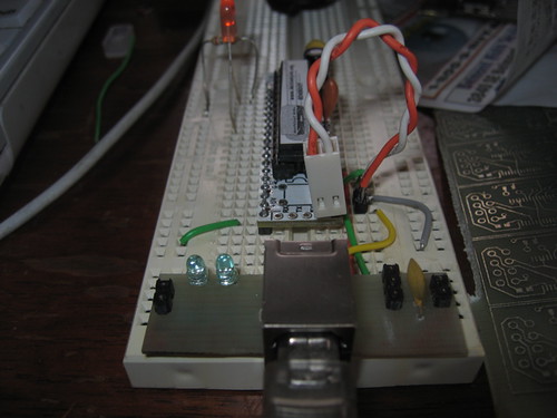
    I sent my son to his mom’s with one of the USB Serial boards I built along with a breadboard, an RBBA a pile of resistors and an led array. I thought about this arrangement and decided that I would try to build a breadboard attached programmer that would not be dangling off the edge of the board and in the way.

    I am wondering if this isn’t the way to go with the seminar kits.

    Board Positive (link to rev A board at 600%)

    I am considering a rev B. The tx and rx are reversed and I think I should put 3 pin headers on the power rails. I am also thinking about putting the 3.3v on the inner rail and the 5V on the outer rail on the positive side.

    I also made a couple of these but I am missing something and this one doesn’t work (yet)

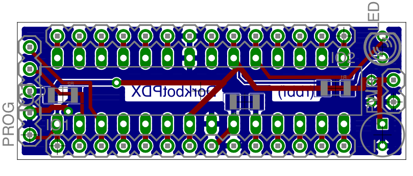
  • A single sided ft232rl based arduino programming board.

    I was so happy with the boards I did the other day that I decided to make some small boards for the ft232 so that aidan would have a programmer for his breadboard RBBA. I made 20 of these boards so if anyone wants one they can order the following parts to the group order.

    QTY Supplier Part number description cost
    1

    DIGIKEY 604-00043-ND IC FTDI FT232RL USB-SRL 28-SSOP 4.02
    1

    DIGIKEY 151-1121-ND CONN USB JACK TYPE B HORIZON R/A .85
    1

    DIGIKEY 490-1035-1-ND FERRITE CHIP 30 OHM 1000MA 0603 .06
    3

    DIGIKEY 399-1169-1-ND CAP .10UF 50V CERAMIC X7R 0805 .15
    2

    DIGIKEY RHM220ARCT-ND RES 220 OHM 1/8W 5% 0805 SMD .07
    2

    DIGIKEY 475-1400-ND LED 3MM 570NM GREEN CLR RADIAL .12


    Link to board image at 600%

  • Adding and burning a different bootloader to the Arduino with the Arduino.

    Q

    Ok so its cool to have a programmer (http://www.dorkbotpdx.org/blog/feurig/dorkbotpdx_arduino_programmer) that you can use standalone but what is the best way to know that the bootloader you just burned works?

    A

    You use it.

    I thought I would write this up for a couple of reasons. I recently did some work with getting the arduino to work with different hardware and in the process I learned a bit about modding the arduino environment. In particular I want to add the “Adaboot” bootloader to the arduino environment, use the burn bootloader feature which was added to version 0010, and test the bootloaders as I was burning them.

    AdaBoot

    The Adaboot bootloader is named after Limor Fried (AKA Lady Ada http://www.ladyada.net/) who made several enhancements to the stock Arduino bootloader. It is well described on the Modern Device Companies page http://moderndevice.com/bootloader.shtml and can be downloaded from wulfden http://www.wulfden.org/freeduino/ADABOOT.shtml. Both sell kits and processors which are preloaded with the adaboot bootloader, The board they sell is a less expensive version of ladyada’s boarduino (at http://www.adafruit.com).
    This method works well because just like programming in Arduino language a lot of the gnarley details like fuse and lock settings are handled by the environment. The other nice thing is that you know that the bootloader works within the environment because you just tested it using the environment.

    Moving the bootloader into place

    When you unzip the archive from wulfden http://www.wulfden.org/freeduino/ADABOOT_7J04b.zip you will find the source code and a premade hex file for the 168 which is named “ATmegaBOOT_168_ng.hex” when you find the bootloader that comes with the arduino for the arduino_ng you will find that its also named “ATmegaBOOT_168_ng.hex” but as you can see from the table on modern device they are most definately not the same. So we are going to name our bootloader adaboot.hex and copy it into the bootloader section on our Arduino installation and then add it to the Arduino IDE.

    $ cp ATmegaBOOT_168_ng.hex /Applications/arduino-0010/hardware/bootloaders/atmega168/adaboot.hex
    $ cd /Applications/arduino-0010/hardware
    $ cp boards.txt boards.txt.stock
    $ open boards.txt
    

    On the mac this last command will bring up the boards.txt file in TextEdit. Copying the code from the decimillia we will create a section with our new bootloader. (the board itself is not important as long as it has the same crystal and processor).


    ##############################################################
    dorkbotpdx.name=Dorkbotpdx Arduino Kit

    dorkbotpdx.upload.protocol=stk500
    dorkbotpdx.upload.maximum_size=14336
    dorkbotpdx.upload.speed=19200

    dorkbotpdx.bootloader.low_fuses=0xff
    dorkbotpdx.bootloader.high_fuses=0xdd
    dorkbotpdx.bootloader.extended_fuses=0x00
    dorkbotpdx.bootloader.path=atmega168
    dorkbotpdx.bootloader.file=adaboot.hex
    dorkbotpdx.bootloader.unlock_bits=0x3F
    dorkbotpdx.bootloader.lock_bits=0x0F

    dorkbotpdx.build.mcu=atmega168
    dorkbotpdx.build.f_cpu=16000000L
    dorkbotpdx.build.core=arduino

    When you reload your arduino software the new “board” will show up like this.

    Burning it using the IDE

    Select the new board.

    Select the serial port used by your arduino

    (I will blog later about why mine shows up as /dev/tty.usbserial-ARDWAYNO)

    Attach your programmer

    and select burn bootloader from the tools menu.

    If all is well it will tell you its done burning the bootloader. Also you will notice that the led on pin 13 says hello (flashes) when you reset the board.

    Testing it using the IDE

    Now load up the blink program from the examples and push the “upload to I/O board” button.

    You should notice that the led pin on 13 flashes while it uploads

    If all is well it will tell you its done.

    And so will your board.

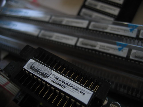
  • Dorkbotpdx Arduino Programmer

    Last week Eric (dr twist) and I got carried away and scored 100 Really Bare Bones Boards (rev A) from wulfden (http://www.wulfden.org/freeduino/freeduino.shtml) for $1.10 a board with shipping, along with the last group order which we ordered enough parts to make the 100 into “kits”. In order to program the 168s I built a programmer around Dean Camera’s “Buttload” (http://www.fourwalledcubicle.com/ButtLoad.php) butterfly based programmer and the 28 pin ziff socket that Paul Stoffregen (http://dorkbotpdx.org/wiki/PaulStoffregen) offered to loan us.

    Unfortunately I miss-wired the socket so I couldn’t program the chips last night. This was a good thing because I actually got to interact with the rest of the group. Our group is growing surprisingly interesting.

    The programmer has 3 modes. In the first mode it simply acts as a programmer. In the second mode it pretends to be a programmer but stores the programs and fuse bits settings in its on board eeprom. This can then be programmed independently of the host. This third mode was the reason that I chose to use this software. I can loan the programmer with the arduino to anyone in th group who needs it.

    Theory

    The programmer has 3 major components. The ftdi FT232R, the Atmel Butterfly, and the “Buttload” software. Looking Dean Cameras Buttload site http://www.fourwalledcubicle.com/ButtLoad.php; and a site by Nard Awater which talks about turning the butterfly into a usb device http://aplomb.nl/TechStuff/BLBF/BLBF.html. I grabbed one of my 3 butterflies, my last unused ftdi breakout board and figured (along with Paul’s offering to loan us a ZIF socket) I would have a programmer by Monday.

    Practice

    Butterfly/FTDI connection

    The butterfly contains an on-board level shifting circuit that inverts the RS232 signals and provides the negative swing by charging a capacitor. The technique used by Nard Awater to communicate with the butterfly is to short the capacitor to ground and then program the ftdi chips to invert the txt and rxd signals. Like many hardware utilities this requires an OBSCENING windows machine. Since I had to dig up an old laptop to upgrade the flash on my Xbee radios I was able to do it. The utility on the FTDI web site http://www.ftdichip.com/Resources/Utilities.htm is called MPROG and it lets you invert the signals, configure the behavior of the CBUS lines, and rename the chip to something you can remember (in this case my butterfly shows up as /dev/tty.usbserial-MYBUTT01).

    I shorted the capacitor (c300) on the butterfly connected the TXD, RXD and Ground directly to the serial port (grey cable in photo).

    Even though windows was required I still prefer this method to removing the level shifting circuit (Though I hear Nick Lott has done it I have destroyed butterflies and never succeeded in this method). It also beats building both ends of the rs232 standard to move serial less than 2 inches.

    power

    I also wired the 3.3v out on the FT232 board to the butterfly to provide power.

    upload name portion of the standard butterfly firmware. It took me a while to figure out that the firmware requires that you set up the baud rate to 19200 baud and I wound up modifying 2 butterflies in the process.

    Firmware

    The firmware for the programmer is on avrfreaks http://www.avrfreaks.net/index.php?module=Freaks%20Files&func=viewFile&id=2419&showinfo=1
    and like all avrfreak’s downloads you will need to register and log in.
    The butterfly bootloader has a magic handshake going on that I can never figure out right but it goes something like select jump to bootloader on the board, load startup avrdude. Press and the joystick on the board until it starts and then let go. (it was pretty late by the time I got to this part so I will have to revisit this when I do another butterfly firmware upgrade).

    Connecting the socket.

    I adapted the generalized circuit described in Awaters zip file.

    In order to use the ISP programmer the socket also requires a VCC AVCC and ground to be wired. While the BUTTLOAD programmer can produce the xtal1 signal it is extremely slow and Dean doesn’t recommend it except for foobared fuze recovery (thats why its called recovery mode). So I wired a 16mhz ceramic resonator to the socket as well.

    It BURNS.

    I wasnt able to test my wiring until I went to the dorkbot meeting (we meet every two weeks) and Paul brought his 28 pin Zif. I plugged it in and put one of our brand new atmega168s in it. Before I could get the cabling done and fire up a window to program it I touched the new chip and burned my finger. I pulled the chip and went back to the conversation I was having until I could get the burner home and check my work. If anyone really demanded a bootloader, I could have done it the old way by plugging the new chip into my Arduino and burning it with my Avrisp-mkII.
    Once I got it home I noticed that the socket I had installed was not cut down to 28 pins but 32! On the right side I had counted from the top end. Once this was remedied I went to checking out the software.

    No Really

    When I fired up avrdude I began to get sync errors. I went back to the lists and the manual and tried varying the programming speed and the baud rates. I finally decided to test the programming to the memory and this worked fine. So I went back to the output side of the circuit and found that the SCK and the MISO lines were reversed. When I tried the actual chip again it said no chip was present. I reread the manual made notes for myself and called it a night.
    In the morning it was pretty clear. I had assumed for some reason that the programmer would provide a complete reset but then realized that most targets would have a 10 k pullup and indeed the reset in the default configuration tristates so that it can be left in place.The 10k pullup resitor on the reset line can be omited as long as you remember to set the RESET mode to LOGIC in the settings menu on the programmer. Things worked fine after that.

  • Arduino (adaboot) Programmer.

    My Bulky Prototype
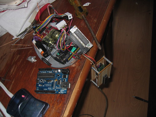
I was using the programming half of a a bulky prototype that I have been working on to program one of the mice from “Thing-a-day” Day 1 and I looked at the pile hanging precariously off of the coffee table and thought to myself.

    “I need to just build one of these. “


    The finished product
    Modifying Sparkfun Board. to fit in the box the input side
    flea assembly blinkin lights in place
    test run Translucence done

    So I did.

    The programmer is based on the Auto-Reset Hack and the AdaBoot bootloader. The reset is pulled by putting a capacitor on the DTR line of the serial interface which is also the bootloader interface. Most people put the cap on the Arduino but I put it on the programmer (where it belongs). This programmer was built using the ftdi ft232rl breakout board sold by sparkfun. I had to trim it down to get it to fit in the pretty blue box i bought at Tap Plastics. The chip out of the box presents two of its 4 gpio (general pourpose i/o) pins to indicate when serial is being sent and recieved. I wired a pair of very bright leds that I had to them and then tried to pipe the light to the corners using some translucent plastic tubes and hot glue. It looks pretty cool!