by on Dorkbot

Note: This work is ongoing see the Benito info page for current info…

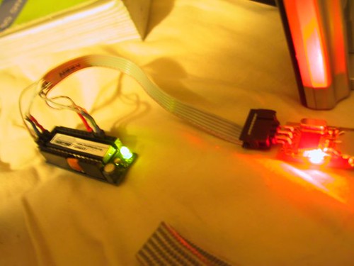
SPI4 is a MyUSB based firmware for the at90usb family of processors.

This program is the core of a programmer that I am working on which uses the Benito board to do in circuit programming (ISP) on the Atmel AVR and 8X51 microcontrollers. It uses the the a feature of atmels USART module called “Master SPI Mode” as described in Atmel’s Application Note #317 (http://www.atmel.com/dyn/resources/prod_documents/doc2577.pdf) (1). The MegaXX8 family and the at90usb series of chips all support this feature.

Setting up the USART

The USART is configured by setting the Uart Mode SELect bits in the UCSRxC register, setting the TXEN and RXEN bits in UCSRxB, and setting the Baud Rate Register (UBRRx)


/* Setup USART1 in master SPI mode */
UBRR1 = 0; /* apparently this needs to be 0 during setup */
UCSR1B = (1<<RXEN1) | (1<<TXEN1);
UCSR1C = (1<<UMSEL11) | (1<<UMSEL10);
/* Calculated value from appnote code. ((CPUFREQ/(2*BPS))-1) */
UBRR1 = ((F_CPU/(20000))-1);

The USART takes care of setting the direction of the MOSI and MISO pins but you are responsible for putting the Clock pin into output mode.

SPI_CLK_PIN_DDR |= _BV(SPI_CLK_PIN);
// SPI_CLK_PIN_PORT |= _BV(SPI_CLK_PIN); // if a known state is needed

If you are using the slave select mechanism you will also need to assign a pin to do the slave select and set it to output mode. On the slave system the SPI pins will tri-state until SS is pulled low.

SPI_SS_PIN_DDR |= _BV(SPI_SS_PIN);
SPI_SS_PIN_PORT |= _BV(SPI_SS_PIN); // PULL Slave Select HIGH

Writing and Reading the data.

Reading and writing the USART in this mode is almost identical to serial transmission with one exception. As the serial is clocked out of the data register incoming data is clocked in.


/*-----------------------------------------------------------------spiOut(value)
* Moves the a byte to SPI and read one back.
*-----------------------------------------------------------------------------*/


unsigned char spiOut(unsigned char value) {

// Wait for empty transmit buffer.
do {} while( (UCSR1A & (1<<UDRE1)) == 0 );
// Send data.
UDR1 = value;
// Wait for transfer to complete and return received value.
do {} while( (UCSR1A & (1<<RXC1)) == 0 );
return UDR1;
}

SPI4: a USB(serial) to SPI converter

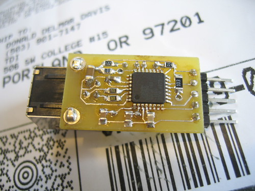
The attached code contains a MyUSB based program called SPI4 it is complete in that it contains copies of the MyUSB library files used. It contains an X-Code project and a make file. If you have an avr-gcc toolchain and dfu-programmer you can “make program” or you can build the xcode project with the program target. It has been tested against the benito at90usb162 board (which you can purchase here or through the dorkbotPDX group order) but should run with minor modifications on the USBKey.

ReadChip: Using the USB to SPI converter.

In the ReadChip directory in the attached code there is an example of reading the signature and fuse bits on an AVR. It is currently built only for the mac but if you bracketed the /* >>> Mac Specific >>>>> */ parts of the code with #ifdefs for your posix platform (anything not redmond based). It should port just fine.

After opening the serial port as a stream write then read a byte at a time. All avr SPI/ISP interactions are done 4 bytes at a time; usually with the second or third return byte being the sync byte and the third and or fourth bytes being the return value.


static int doTheOldInOut (int fileDescriptor, char *inBuff, char *outBuff) {
int i=0;
for (i=0;i<4;i++) {
 if (write(fileDescriptor, outBuff+i, 1)>0) {
  //debug printf(">%02X>n",outBuff[i]&0x000000ff);
  if ((read(fileDescriptor, inBuff+i, 1)>0)){
   //debug printf("<%02X<",inBuff[i]&0x000000ff);
  } else {
   printf("Error reading from Device - %s(%d).n", strerror(errno), errno);
   continue;
  }
 } else {
  printf("Error writing to Device - %s(%d).n", strerror(errno), errno);
  continue;
 }
}
return 1;
}

To read the fuses for example send the four bytes {0x50,0x00,0x00,blah} (where the last byte doesnt matter) and check to make sure that the first byte is echoed back;


doTheOldInOut(fileDescriptor, inBuff, kGetLowFuseBits);
if (inBuff[1]==0x50){
  FuseLow=inBuff[3]&0x000000ff;
}

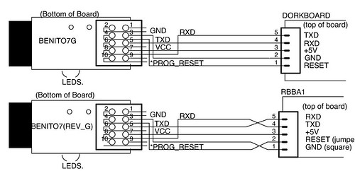
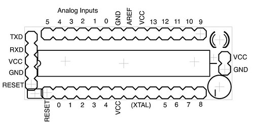
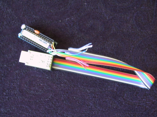
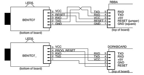
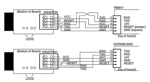
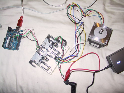
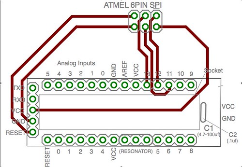
To wire the benito to the dorkboard or another arduino based board use the following configuration. The center 6 pins of the Benito7(rev g) form a standard atmel 6pin programming header.

Output.

Try #1
Resetting Target
Looking for Sync

Got Sync!

ISP initialized successfully.
Signature[1]=1E
Signature[2]=94
Signature[3]=06
FuseLow=FF
FuseHigh=DD
FuseExtended=F8
LockBits=CF
ISP port closed.

Source

See Also:

Footnotes:

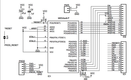
(1) The original benito design exposed the serial pins on portd and the SPI pins from port B. The final rev of the Benito7(g) takes this mode into consideration and exposes all of port D instead.

by on Dorkbot

Missing Links.

One of the joys of the Arduino Cult Induction Sessions is that mistakes and omissions are generally caught on the spot and there is no lag between the steps we forgot to include an the instructions and the person who’s board isn’t working.

One of those steps is the Reset Jumper on the Dorkboard. The jumper is a compromise reached between myself and Brian Riley of Wuflden and Paul Badger of Modern Devices. The programmers that they are working on and the next generation of freeduino boards will have a standard pinout that the dorkboard complies with. In addition they are using the .1uf auto reset capacitor on their boards. In order to maintain compatibility with their boards and programmers I added pads for either a jumper or a small surface mount capacitor between the programming header. If you are using a dorkbotpdx programmer you need to solder this jumper for the programmer to work.

It seems that I also failed to upload a schematic for the final revision of the dorkboard.

(click to view a larger sized image)

I still have not put together a complete set of instructions for building the Dorkboard outside of the induction workshops. Breedx however has started one at http://dorkbotpdx.org/dorkboard_assembly_tutorial.

I did, however, manage to add an updated cable diagram to the cables page.

Moments of Truth.

If you didn’t make it through an induction or decided to go it alone: here is a brief description of what should happen once you have your dorkboard put together.

On your cable if you are looking at the bottom of the benito board the wires will be (from bottom to top) nc,nc,RXD,VCC,nc,TXD,RESET,GND,nc, and nc (where nc is “not connected”).

Power it up.

Plugging your programmer into the usb port and hooking up the power and the ground wires (to the center post and the pin down from it on the programming header) should give you some results on a board whos processor has the dorkbotpdx adaboot lable. These processors were programmed twice: once with the adaboot boot loader, and once with a test program called blink. When you apply power to the board the led should blink erratically to tell you that its in the bootloader and then steadily.

If you are running windows windows will ask you for a driver for the device. Copy the text from http://dorkbotpdx.org/blog/feurig/arduino_cult_induction_rev3_followup into a file called benito7g.inf and select that file. That file tells windows to use its built in drivers. Why it cant figure that out on its own is beyond me.

Download the software.

Download the software from http://www.arduino.cc/en/Main/Software and open the arduino application. In the tools menu select the new serial port and under board select the “Arduino Decimilia”. (If linux doesnt show the serial port check out this thread.) Then, under File->SketchBook->Examples->Digital select the blink program. This is the program that your Dorkboard should be running.

Upload your program.

Once the reset is wired (including the reset jumper) pressing the “upload to io board” button on on the bar above the code will cause the led to blink sporadically to indicate that it is going entering the bootloader. Then, if the serial lines (txd and rxd) are loaded correctly, there should be blinking lights all around followed by a message at the bottom indicating the size of the program that was just loaded.

by on iphone

I just spent the weekend with a few people who knew a lot more about programming the iphone than I did and several people that knew about as much as I did. I can tell you that the Portland group got the best of satellite category for our collectively built app.

(If you look behind the sf group you can see the Portland and Seattle groups in the background)

But given Apple’s NDA I can’t tell you much else.

by on Dorkbot

This is something to chew on while I put together some bigger pieces.

See also AVR151 at http://www.atmel.com/dyn/products/app_notes.asp?family_id=607

/*
* This program lights pins 2-9 with data recieved via the spi port.
* it also resends the bytes back through the port.
*
* Based on Atmel application note avr151.
*
* Donald Delmar Davis, Tempus Dictum, Inc.
*/
#define SPI_SCK 13
#define SPI_MISO 12
#define SPI_MOSI 11
#define SPI_SS 10

void SPI_Init(void);
unsigned char SPI_ReadWrite(unsigned char data);
unsigned char SPI_Read(void);

#define SPI_DONTCARE (0x00)
unsigned char theByte = SPI_DONTCARE;

// init as SPI-Master
void SPI_MASTER_Init(void) {
pinMode(SPI_SCK,OUTPUT);
pinMode(SPI_MOSI,OUTPUT);
pinMode(SPI_SS,OUTPUT);
pinMode(SPI_MISO,INPUT);

// INIT interface, Master, set clock rate fck/4
SPCR = (1<<SPE)|(1<<MSTR)|(0<<SPR0)|(0<<SPR1);
// enable double rate
SPSR = (1<<SPI2X); // we will now gain fck/2 instead of fck/4
}

void SPI_SLAVE_Init(void) {
pinMode(SPI_SCK,INPUT);
pinMode(SPI_MOSI,INPUT);
pinMode(SPI_SS,INPUT);
pinMode(SPI_MISO,OUTPUT);

// INIT interface, Master, set clock rate fck/4
SPCR = (1<<SPE)|(0<<SPR0)|(0<<SPR1);
// enable double rate
SPSR = (1<<SPI2X); // we will now gain fck/2 instead of fck/4
}

unsigned char SPI_ReadWrite(unsigned char data) {
// set data to send into SPI data register
SPDR = data;
// Wait for transmission complete
while(!(SPSR & (1<<SPIF)));
// return data read from SPI (if any)
return SPDR;
}

unsigned char SPI_Read(void) {
return SPI_ReadWrite(SPI_DONTCARE);
}

void setup() {

SPI_SLAVE_Init();
pinMode(2,OUTPUT);
pinMode(3,OUTPUT);
pinMode(4,OUTPUT);
pinMode(5,OUTPUT);
pinMode(6,OUTPUT);
pinMode(7,OUTPUT);
pinMode(8,OUTPUT);
pinMode(9,OUTPUT);

}

void loop(){
digitalWrite(2,theByte & (1<<0));
digitalWrite(3,theByte & (1<<1));
digitalWrite(4,theByte & (1<<2));
digitalWrite(5,theByte & (1<<3));
digitalWrite(6,theByte & (1<<4));
digitalWrite(7,theByte & (1<<5));
digitalWrite(8,theByte & (1<<6));
digitalWrite(9,theByte & (1<<7));

theByte=SPI_ReadWrite(theByte);

}


by on Dorkbot

This group got further along than any induction so far. I was really happy and thank every one who came out. I have a couple of things here as a follow up that might be helpfull and if you leave comments or email me I can follow up here as well.

First here is a map of the dorkboard pins using the arduino pin numbering system.

Also here is the .inf file which makes the Benito use the built in windows drivers.


; Windows MyUSB USB to Serial Setup File
; Copyright (c) 2000 Microsoft Corporation

[Version]
Signature="$Windows NT$"
Class=Ports
ClassGuid={4D36E978-E325-11CE-BFC1-08002BE10318}
Provider=%COMPANY%
LayoutFile=layout.inf
DriverVer=06/06/2006,1.0.0.0

[Manufacturer]
%MFGNAME% = ManufName

[DestinationDirs]
DefaultDestDir=12

[ManufName]
%Modem3% = Modem3, USBVID_03EB&PID_204B

;------------------------------------------------------------------------------
; Windows 2000/XP Sections
;------------------------------------------------------------------------------

[Modem3.nt]
CopyFiles=USBModemCopyFileSection
AddReg=Modem3.nt.AddReg

[USBModemCopyFileSection]
usbser.sys,,,0x20

[Modem3.nt.AddReg]
HKR,,DevLoader,,*ntkern
HKR,,NTMPDriver,,usbser.sys
HKR,,EnumPropPages32,,"MsPorts.dll,SerialPortPropPageProvider"

[Modem3.nt.Services]
AddService=usbser, 0x00000002, DriverService

[DriverService]
DisplayName=%SERVICE%
ServiceType=1
StartType=3
ErrorControl=1
ServiceBinary=%12%usbser.sys

;------------------------------------------------------------------------------
; String Definitions
;------------------------------------------------------------------------------

[Strings]
COMPANY="Tempus Dictum, Inc"
MFGNAME="Donald Delmar Davis"
Modem3="USB Virtual Serial Port"
SERVICE="USB Virtual Serial Port CDC Driver"

by on Dorkbot

Here is a small example of using the arduino/wiring platform to control things in the real world.

A pretty good reference for the controlling stepper motors can be found at.

http://en.nanotec.com/steppermotor_animation.html

The following Circuit fleshes out the sketch at the site above.

And finally here is the sketch to make it go.

/* Rapha Roller Race Controller.
 * The Rapha Roller Race Controller is for a 4 bike 500 meter race The bikes are on rollers which
 * produce pulses. The pulses are used to drive a dial per bicycle which is controlled by
 * a unipolar stepper motor, the dials are geared such that two pulses two each one
 * motor half "step" results in 500 meters per complete revolution.
 *
 * This program uses wirings External Interrupt Mechanism. The program loop is used to
 * watch the control panel and move the dials to a starting position.
 *
 * NOTE: RABBID PROTOTYPE! This was done in a very make it work NOW mode.
 * I am certain there are more elegant solutions.
 *
 * Author Donald Delmar Davis, Tempus Dictum Inc.
 */

#define NMOTORS 4
#define NPINS 4
#define NSTATES 8
#define HALFSTEP 1
#define FULLSTEP 0
#define FORWARDSTEP  1
#define BACKWARDSTEP 0

/*------------------------------------------------------------------------------------
 * Pin Mapping
 */

#define SWITCH1PIN  34
#define SWITCH2PIN  35
#define SWITCH3APIN 49
#define SWITCH3BPIN 50
#define LEDPIN 48
#define BIKE1 36
#define BIKE2 37
#define BIKE3 38
#define BIKE4 39

int motorPins[NMOTORS][NPINS]= {
  { 11,  9, 10,  8  } , // ccw is forward
  { 15, 13, 14, 12  },
  { 20, 22, 21, 23  },
  { 16, 18, 17, 19  },
  //  { 8, 10,  9, 11}, // cw is forward
  //  {12, 14, 13, 15},
  //  {23, 21, 22, 20},
  //  {19, 17, 18, 16},
};

int pulsesPerStep=2;
volatile int pulseCount[4]={0,0,0,0};
volatile int pulseMod[4]={2,2,2,2};
int ledState = HIGH;
int switchState=LOW;
int delayTime = 10;

int motorState [NMOTORS] = {0,0,0,0};

int pinStates[NSTATES][NPINS]= {
  { HIGH,LOW ,LOW ,LOW   } ,
  { HIGH,HIGH,LOW ,LOW   },
  { LOW ,HIGH,LOW ,LOW   },
  { LOW ,HIGH,HIGH,LOW   },
  { LOW ,LOW ,HIGH,LOW   },
  { LOW ,LOW ,HIGH,HIGH  },
  { LOW ,LOW ,LOW ,HIGH  },
  { HIGH,LOW ,LOW ,HIGH  }
};

/* -------
*/
void stepit (int motorNum, int stepDir, int stepSize) {
  int stateSkip=2;
  int pin;

  if (stepSize==HALFSTEP) stateSkip=1;

  if (stepDir==FORWARDSTEP) {
    motorState[motorNum] += stateSkip;
    if (motorState[motorNum] >= NSTATES) {
      motorState[motorNum]=0;
    }
  }
  else {
    if (motorState[motorNum] < stateSkip){
      motorState[motorNum] = NSTATES-1;
    }
    else {
      motorState[motorNum] -= stateSkip ;
    }
  }

  for (pin=0 ; pin < NPINS ; pin++) {
    digitalWrite(motorPins[motorNum][pin], pinStates[motorState[motorNum]][pin]);
  }
}
/*---------------------------------------------------------------------------------setup()
 *
 *
 *
 */
void setup() {
  int motor;
  int pin;
  for (motor=0;motor<NMOTORS; motor++){
    for (pin=0; pin<NPINS; pin++){
      pinMode(motorPins[motor][pin],OUTPUT);
      digitalWrite(motorPins[motor][pin],pinStates[motorState[motor]][pin]);
    }
  }
  pinMode(LEDPIN,OUTPUT);
  pinMode(BIKE1,INPUT);
  pinMode(BIKE2,INPUT);
  pinMode(BIKE3,INPUT);
  pinMode(BIKE4,INPUT);
  pinMode(SWITCH1PIN,INPUT);
  pinMode(SWITCH2PIN,INPUT);
  pinMode(SWITCH3APIN,INPUT);
  pinMode(SWITCH3BPIN,INPUT);

  attachInterrupt(4, bike1, RISING); //
  attachInterrupt(5, bike2, RISING); //
  attachInterrupt(6, bike3, RISING); //
  attachInterrupt(7, bike4, RISING); //
//  Serial.begin(9600);             // Starts Serial to print data

}

/*-----------------------------------------------------------------------------------------
 ************************************* Interrupt Handlers *********************************

 */
/*----------------------------------------------------------------------------------bike1()
 */
void bike1() {
  //Serial.print("bike1 ");
  ++pulseCount[0];
  if ((--pulseMod[0]) == 0 ){
    stepit(0,FORWARDSTEP,HALFSTEP);
    pulseMod[0]=pulsesPerStep;
  }
}
/*-----------------------------------------------------------------------------------------
 */
void bike2() {
  //Serial.print("bike2 ");
  ++pulseCount[1];
  if ((--pulseMod[1]) == 0 ){
    stepit(1,FORWARDSTEP,HALFSTEP);
    pulseMod[1]=pulsesPerStep;
  }
}
/*-----------------------------------------------------------------------------------------
 */
void bike3() {
  //Serial.print("bike3 ");
  ++pulseCount[2];
  if ((--pulseMod[2]) == 0 ){
    stepit(2,FORWARDSTEP,HALFSTEP);
    pulseMod[2]=pulsesPerStep;
  }
}
/*-----------------------------------------------------------------------------------------
 */
void bike4() {
  //Serial.print("bike4 ");
  ++pulseCount[3];
  if ((--pulseMod[3]) == 0 ){
    stepit(3,FORWARDSTEP,HALFSTEP);
    pulseMod[3]=pulsesPerStep;
  }
}
/*-----------------------------------------------------------------------------------------
 ************************************* Main Loop ******************************************
 *---------------------------------------------------------------------------------------*/

/*-----------------------------------------------------------------------------------------
 *
 */

void loop() {
  int currentMotor;
  currentMotor=(digitalRead(SWITCH1PIN)*2)+digitalRead(SWITCH2PIN) ;
  switchState=digitalRead(SWITCH3BPIN);
  if (switchState==HIGH) {
     stepit(currentMotor,FORWARDSTEP,HALFSTEP);
   }
   switchState=digitalRead(SWITCH3APIN);
   if (switchState==HIGH) {
     stepit(currentMotor,BACKWARDSTEP,HALFSTEP);
   }
   ledState=!ledState;
   digitalWrite(LEDPIN,ledState);
   delay(delayTime);
}

by on Dorkbot

In the course of the Arduino Cult Induction series and the group purchases, I have evolved several versions of the DorkbotPDX programmer and released them into the wild. Unfortunately the pinouts for the programming cable have evolved with the programmers so the cables are unique to each. With the batch of programmers we just purchased this will settle down Though the pinout may not make sense in this particular case it will be the same for at least 1000 boards.

Here is a quick guide to cables for the DorkbotPDX programming boards for the rbba and the dorkboard.

Benito7 rev G
(1000 Currently being released into the wild)

Benito7 rev a
(26 known to be in the wild 16 from Sunstone 10 hand rolled)

Cables for the benito7 should look like this.

Winston (rev3) — hand rolled,

(at least 50 known to be have been released into the wild)

The winston board was my first usb to serial programming board.

by on Avr DevelopmentWiring/Arduino

Rapha Sportswear has a stationary race controller prototype that they need replicated for an event next week. The first step int this process was to break out the original design into 3 boards one for input processing one for the stepper drivers and one for the processor itself. Since the customer wanted to be able to modify the code themselves in the future and expand the system an Arduino or Wiring compatible board will be used.

(The completed project)

Motor Boards

The motor boards consisted of 4 darlington transistors on the best performing heat sinks I could find.

The I/O – Processor Board.

The I/O Processor board consisted of to schmidt triggers to clean up the input and a usb to serial connection for programming and future use. The board also has 3 free ports for future use.