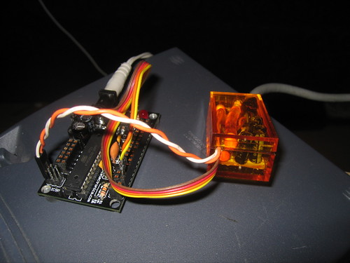
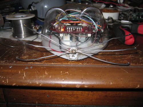
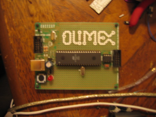
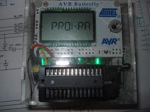
Last week Eric (dr twist) and I got carried away and scored 100 Really Bare Bones Boards (rev A) from wulfden (http://www.wulfden.org/freeduino/freeduino.shtml) for $1.10 a board with shipping, along with the last group order which we ordered enough parts to make the 100 into “kits”. In order to program the 168s I built a programmer around Dean Camera’s “Buttload” (http://www.fourwalledcubicle.com/ButtLoad.php) butterfly based programmer and the 28 pin ziff socket that Paul Stoffregen (http://dorkbotpdx.org/wiki/PaulStoffregen) offered to loan us.
Unfortunately I miss-wired the socket so I couldn’t program the chips last night. This was a good thing because I actually got to interact with the rest of the group. Our group is growing surprisingly interesting.
The programmer has 3 modes. In the first mode it simply acts as a programmer. In the second mode it pretends to be a programmer but stores the programs and fuse bits settings in its on board eeprom. This can then be programmed independently of the host. This third mode was the reason that I chose to use this software. I can loan the programmer with the arduino to anyone in th group who needs it.
Theory
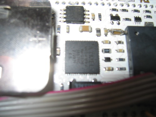
The programmer has 3 major components. The ftdi FT232R, the Atmel Butterfly, and the “Buttload” software. Looking Dean Cameras Buttload site http://www.fourwalledcubicle.com/ButtLoad.php; and a site by Nard Awater which talks about turning the butterfly into a usb device http://aplomb.nl/TechStuff/BLBF/BLBF.html. I grabbed one of my 3 butterflies, my last unused ftdi breakout board and figured (along with Paul’s offering to loan us a ZIF socket) I would have a programmer by Monday.
Practice
Butterfly/FTDI connection
The butterfly contains an on-board level shifting circuit that inverts the RS232 signals and provides the negative swing by charging a capacitor. The technique used by Nard Awater to communicate with the butterfly is to short the capacitor to ground and then program the ftdi chips to invert the txt and rxd signals. Like many hardware utilities this requires an OBSCENING windows machine. Since I had to dig up an old laptop to upgrade the flash on my Xbee radios I was able to do it. The utility on the FTDI web site http://www.ftdichip.com/Resources/Utilities.htm is called MPROG and it lets you invert the signals, configure the behavior of the CBUS lines, and rename the chip to something you can remember (in this case my butterfly shows up as /dev/tty.usbserial-MYBUTT01).
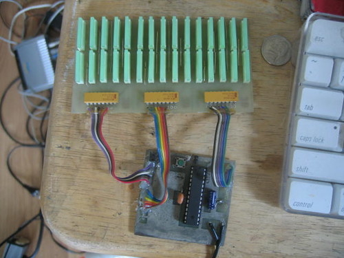
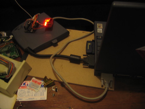
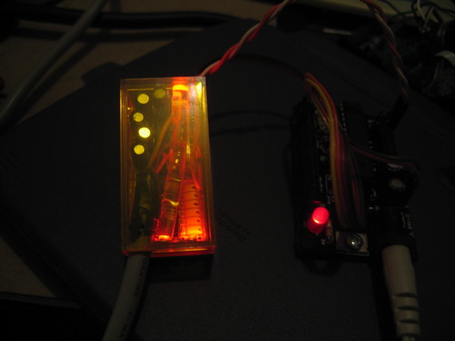
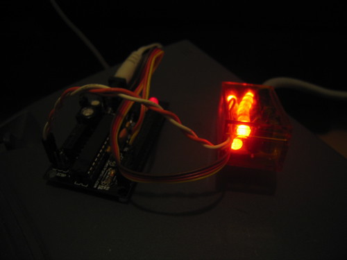
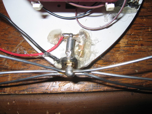
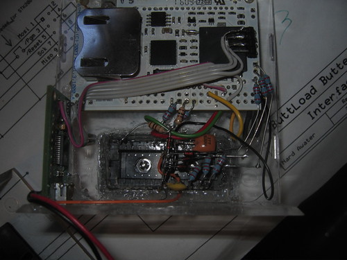
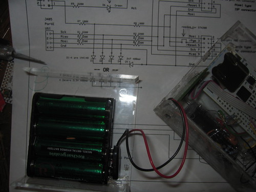
I shorted the capacitor (c300) on the butterfly connected the TXD, RXD and Ground directly to the serial port (grey cable in photo).
Even though windows was required I still prefer this method to removing the level shifting circuit (Though I hear Nick Lott has done it I have destroyed butterflies and never succeeded in this method). It also beats building both ends of the rs232 standard to move serial less than 2 inches.
power
I also wired the 3.3v out on the FT232 board to the butterfly to provide power.

 upload name portion of the standard butterfly firmware. It took me a while to figure out that the firmware requires that you set up the baud rate to 19200 baud and I wound up modifying 2 butterflies in the process.
Firmware
The firmware for the programmer is on avrfreaks http://www.avrfreaks.net/index.php?module=Freaks%20Files&func=viewFile&id=2419&showinfo=1
and like all avrfreak’s downloads you will need to register and log in.
The butterfly bootloader has a magic handshake going on that I can never figure out right but it goes something like select jump to bootloader on the board, load startup avrdude. Press and the joystick on the board until it starts and then let go. (it was pretty late by the time I got to this part so I will have to revisit this when I do another butterfly firmware upgrade).
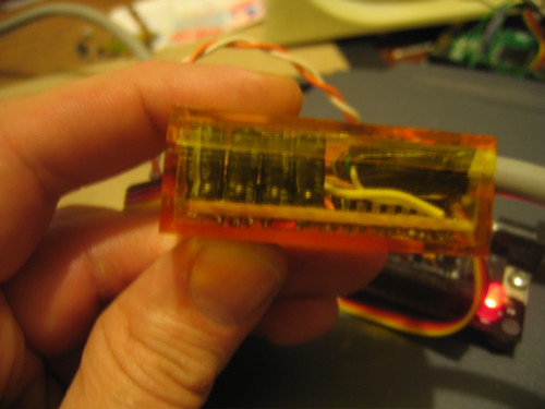
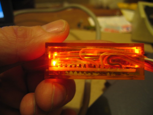
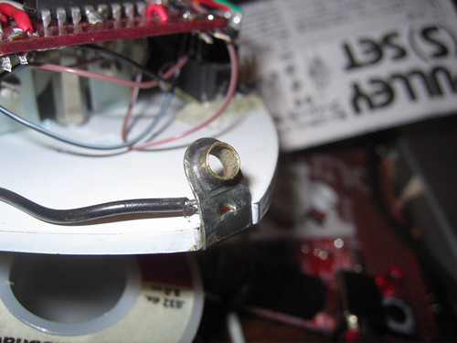
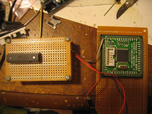
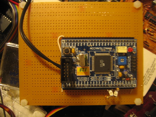
Connecting the socket.
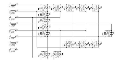
I adapted the generalized circuit described in Awaters zip file.

In order to use the ISP programmer the socket also requires a VCC AVCC and ground to be wired. While the BUTTLOAD programmer can produce the xtal1 signal it is extremely slow and Dean doesn’t recommend it except for foobared fuze recovery (thats why its called recovery mode). So I wired a 16mhz ceramic resonator to the socket as well.
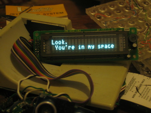
It BURNS.
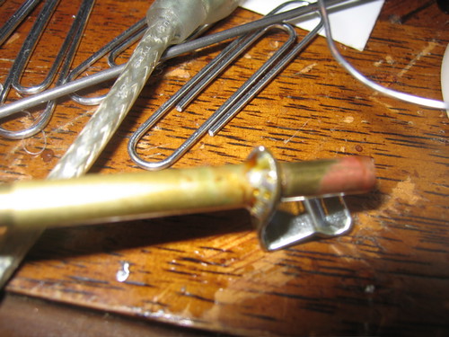
I wasnt able to test my wiring until I went to the dorkbot meeting (we meet every two weeks) and Paul brought his 28 pin Zif. I plugged it in and put one of our brand new atmega168s in it. Before I could get the cabling done and fire up a window to program it I touched the new chip and burned my finger. I pulled the chip and went back to the conversation I was having until I could get the burner home and check my work. If anyone really demanded a bootloader, I could have done it the old way by plugging the new chip into my Arduino and burning it with my Avrisp-mkII.
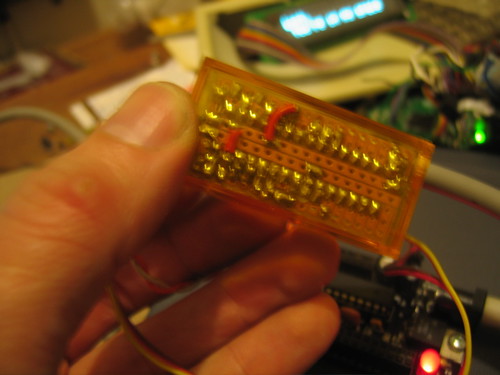
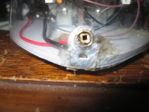
Once I got it home I noticed that the socket I had installed was not cut down to 28 pins but 32! On the right side I had counted from the top end. Once this was remedied I went to checking out the software.
No Really
When I fired up avrdude I began to get sync errors. I went back to the lists and the manual and tried varying the programming speed and the baud rates. I finally decided to test the programming to the memory and this worked fine. So I went back to the output side of the circuit and found that the SCK and the MISO lines were reversed. When I tried the actual chip again it said no chip was present. I reread the manual made notes for myself and called it a night.
In the morning it was pretty clear. I had assumed for some reason that the programmer would provide a complete reset but then realized that most targets would have a 10 k pullup and indeed the reset in the default configuration tristates so that it can be left in place.The 10k pullup resitor on the reset line can be omited as long as you remember to set the RESET mode to LOGIC in the settings menu on the programmer. Things worked fine after that.