Posts Categorized: Dorkbot
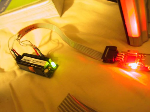
Pretty Pretty.

As it gets dark I find myself needing to get the blinking lights working on my bycycle. I am also reminded of the ever present need to find space where you don’t have to breath what you work with. Three days after casting the first set of lights the apartment still reeks.

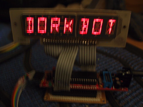
Square Waves Through Round Holes
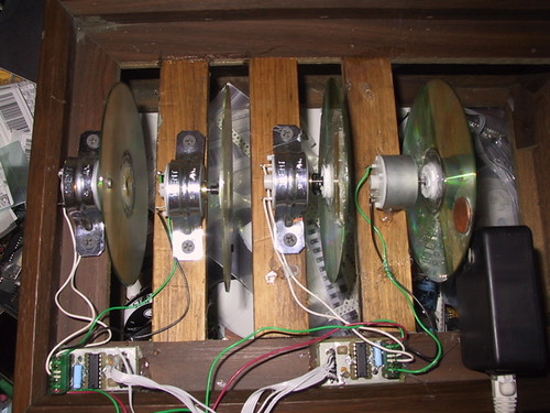
I needed to test the new sensors I am putting on the Rapha stationary bike race controller so I built a 4 bike race “emulator”. As you can hear in the video attached the motor controller test program sounds very blade runnery.
Squiggley is not Bang!
&& ! != ~
There are those days when I am pretty sure I cant program my way out of a brown paper bag.
And then there are those days when I don’t care.
Motorboard Buildout
Uncanny Resemblance….
 image (C) Max Cannnon click to go to redmeat |
That would explain a lot wouldnt it?
Clear as Mud.
I am regularly sending ordinary people to look a the application sections of the datasheets for several electronic parts if they want to know how a part should be used. As I was laying out the motor boards for the weekends workshop I came across the following in the datasheet for the L239(not d) clone that Texas Intruments puts out.
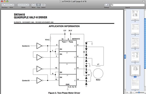
Can you tell where the chip begins and the diagram ends? Can you tell that the diodes are (not really) included in the chip or would you add them to your parts count.?
Build Your own USB to Serial Device
Note: This work is ongoing see the Benito info page for current info…
Introduction
This is a first take on using the Benito board to create an open source USB to Serial converter.
SPI4 USB to SPI converter
Note: This work is ongoing see the Benito info page for current info…